|
|
|
|
|
|
This is a simple circuit using a RS-422/485 receiver/transmitter to receive a signal from the coax S/PDIF-input and to drive the coax S/PDIF-output.
Both the optical (TOSLINK) and the coaxial output can be switched individually either to the optical or the coaxial inputs.
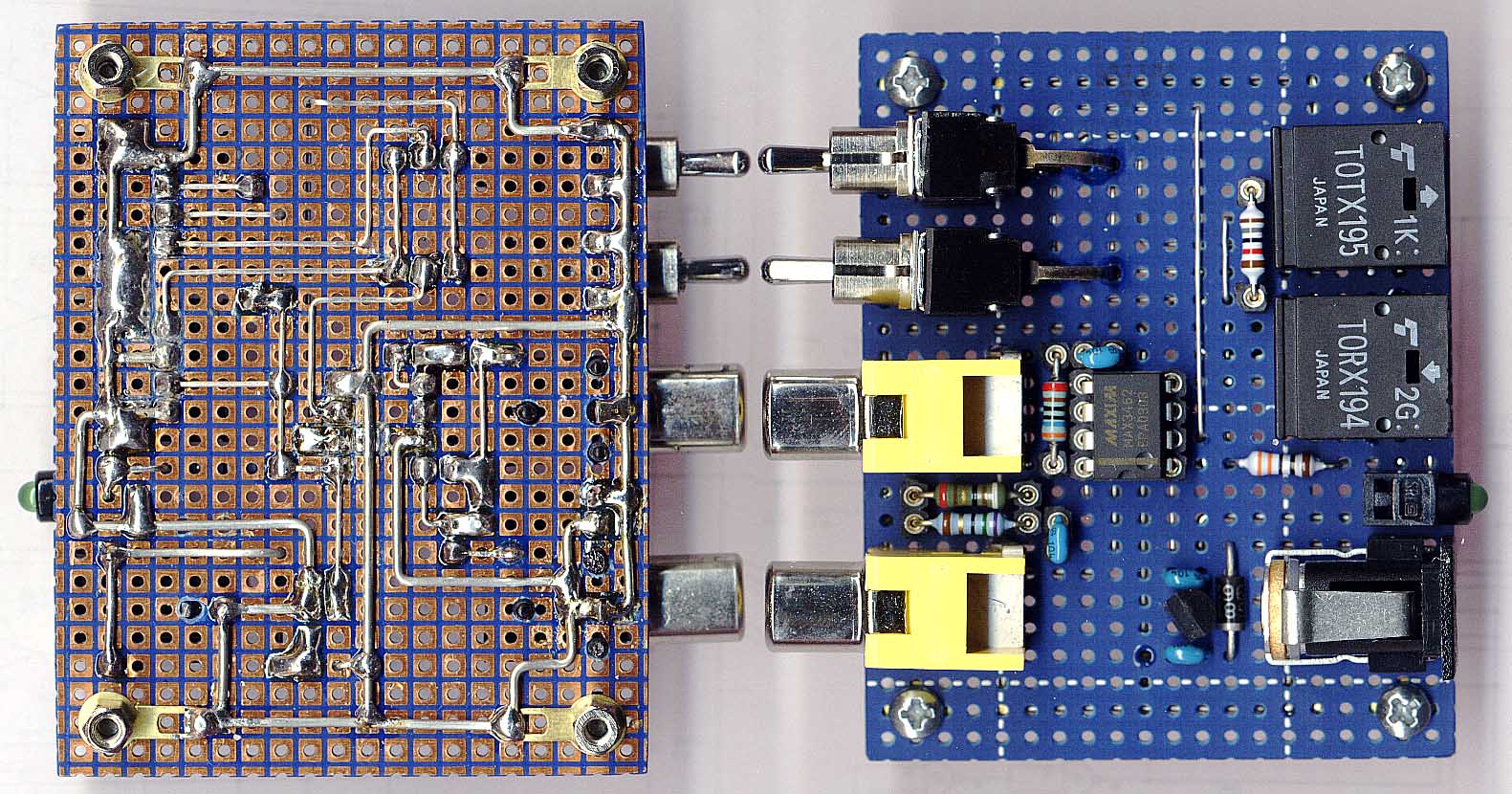
Relatively cheap components can be used for up to 48 kHz sample rate. For up to 96 kHz things become more expensive.
Up to 48 kHz:
Up to 96 kHz:
All components are pin compatible and may alternatively used.
The 96 KHz version does not work properly as the MAX3462 does not work properly! Obviously there is a design error in the MAX3462: When the device is wired as a simple RS-422 repeater (pins 2 and 3 connected, source impedance 75 Ohm, no load) a strong spike after each falling edge can be observed. This might be due to an internal feedback from the RS-422 output to the RS-422 input. I do not have a remedy yet. Currently the full duplex operation with both directions carrying data and the S/PDIF repeater modes are not applicable. (A S/PDIF repeater mode with a detour via TOSLINK works!)
Maxim RS-244/485 Receiver/Transmitter MAX3462
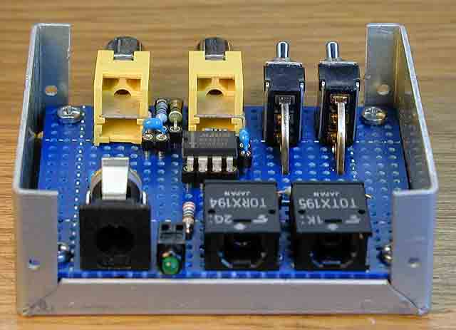
The board is designed to fit in a cheap Teko Al Box 2/A.1 which is shown without a cover here.
| Last update: April, 22nd, 2005 | Questions? Suggestions? Email Me! | Uwe Beis |