|
|
|
|
|
|
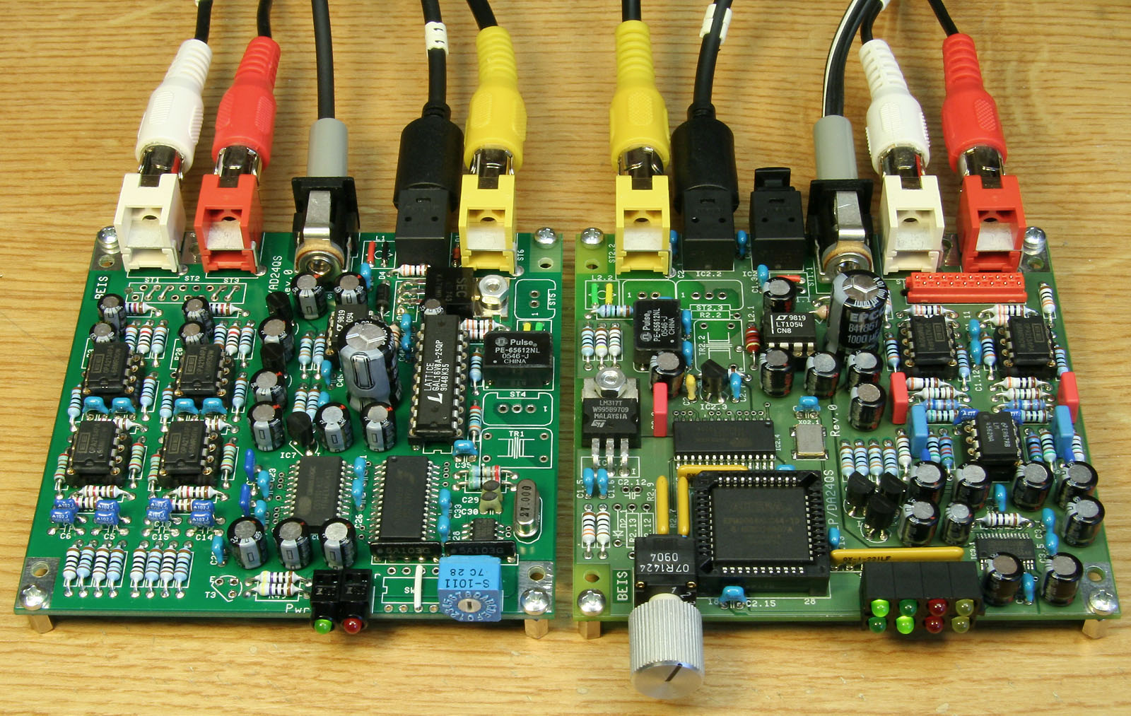 This is a preview for the Analog to Digital Converter
AD24QS and the Digital to Analog Converter DA24QS ("QS"
stands for "Quad Speed"). Both prototypes are working
fine and I think it is time to "allow a first glance on them".
This is a preview for the Analog to Digital Converter
AD24QS and the Digital to Analog Converter DA24QS ("QS"
stands for "Quad Speed"). Both prototypes are working
fine and I think it is time to "allow a first glance on them".
It will still take some time to make kits available. Due to errors and improvements there are minor changes on the prototypes and the next step will be one more set of prototypes based on corrected PCB-layouts.
Click here (or on the photo) for an enlarged view on both devices. (On the left is the ADC, on the right the DAC.)
The ADC is capable of 10 different sample rates up to 192 kHz, set with the switch you can see on the ADC's front:
| Setting | Sample Rate (kHz) | Format | Copyright | |||
| 0 | 16 | Professional | - | |||
| 1 | 22.05 | Professional | - | |||
| 2 | 24 | Professional | - | |||
| 3 | 32 | Professional | - | |||
| 4 | 44.1 | Professional | - | |||
| 5 | 48 | Professional | - | |||
| 6 | 64 | Professional | - | |||
| 7 | 88.2 | Professional | - | |||
| 8 | 96 | Professional | - | |||
| 9 | 192 | Professional | - | |||
| A | 44.1 | Consumer | Not asserted | |||
| B | 44.1 | Consumer | Asserted, original version | |||
| C | 44.1 | Consumer | Asserted, copied version | |||
| D | 48 | Consumer | Not asserted | |||
| E | 48 | Consumer | Asserted, original version | |||
| F | 48 | Consumer | Asserted, copied version |
The first 10 sample rates, with the digital audio signal indicated as "Professional Format", are selected in positions 1 - 9. Positions A - F are indicated as "Consumer Format", where you can select 44.1 kHz or 48 kHz only, but each with the options "no copyright asserted", "copyright asserted, original version" and "copyright asserted, copied version". Using a decimal encoding switch prevents access to the consumer format.
All connections are made on the rear. The optical output device (currently a TOTX179PL) is not specified for 192 kHz, though it works fine on the workbench. The TOTX179PL is discontinued and will probably replaced by TOTX177PL, which unfortunately will not be available within the next month. This, by the way, is one of the reasons why the availability of the next kits will further be delayed.
The digital audio transformer for the coaxial signal is not specified for 192 kHz either, but when you have a look at its frequency response or its pulse transmission characteristics you understand why I unscrupulously use them. They'd be fine for even much, much higher frequencies than 192 kHz.
The AD24QS can be equipped with external professional, balanced audio inputs (XLR) and also with an external switch to select between the on-board, unbalanced Cinch or the external XLR inputs. The connector for the external inputs matches exactly the one on the upcoming new version of the high quality microphone and line preamplifier 2ChPre. This Micro-MaTch connector does not only carry the audio signals but the power supply and a means for gain adjustment, too. On the photo you can see the position for this Micromatch connector, but it is not populated there.
Also, the AD24QS can be equipped externally with a professional, balanced digital audio output XLR (AES-3) or BNC jack. The decoupling transformer and the termination resistors are provided on board.
In order to achieve these many sample rates I had to introduce a more complex logic than on the AD2496. It is still a static circuitry, but too complex for one or two logic gate ICs. So I was forced to use some kind of programmable logic and chose a GAL16V8, the simplest, smallest and cheapest one that is available (except that, in order to save power, I recommend the slightly more expensive quarter power GAL version). In kits, you'll get them programmed.
The preamplifiers are dimensioned for an input sensitivity of 2 VRMS approx. at 100% FS, a usual level e.g. for CD or DVD players.
When the balanced XLR input option is used, the input sensititvity should be reduced to the standard studio level of +4 dBu (1.23 VRMS) plus a reasonable headroom of e.g. 12 dB. I.e., 5 VRMS (+20 dBu) for 100% FS, like the maximum output level of the DA24QS, might be a good choice.
The power supply is 12 VDC and the current consumption is about 180 mA.
For the current circuit diagram of the AD24QS, have a look here. But keep in mind, it is not final and changes every now and then.
The DAC operates over a wide range of sample rates. The S/P-DIF receiver-IC (Cirrus CS8416) is specified from 30 kHz up to 216 kHz, but my sample works even with 16 kHz from the AD24QS (though, at 16 kHz, with a remarkably low SNR at the audio outputs).
8 LEDs on the front indicate some operational states:
Green: Sample Rate < 55.33 kHz (Single Speed, SS)
Green: Sample Rate > 55.33 kHz and < 110.67 kHz (Double Sspeed, DS)
Green: Sample Rate > 110.67 kHz (Quad Speed, QS)
Green: Professional Format
Red: Receive Error or No Signal
Red: No Linear PCM Audio (i.e., the digital signal is a surround sound signal or something like that)
Yellow: Copyright Asserted
Yellow: Emphasis Signalled
Like in the AD24QS, all connections are made on the rear. Also like in the ADC, the optical input device (currently a TORX141PL) is not specified for 192 kHz, though it works fine on the workbench. And once again, like in the ADC, the TORX141PL is discontinued and will probably replaced by TORX174PL, which (guess what...) unfortunately will not be available within the next month.
Last not least, like in the AD24QS, the digital audio transformer for the coaxial signal is not specified for 192 kHz either, but this time I won't repeat the text written above.
I provided 4 digital audio inputs, selectable with a small rotary switch on the front. 3 of the inputs are S/P-DIF inputs and located on the PCB (1 x coax and 2 x optical), for the 4th input a transformer and a termination resistor is provided, but the jack must be connected externally. Thist 4th input is particularly intended as a balanced AES-3 input (XLR), but a second Cinch or a BNC jack can be connected, too.
The logic for the DA24QS is much more complex than the one for the AD24QS. Most important is the need for a sample rate detector. The DAC-IC (Cirrus "Flagship" CS4398) must be supplied with an information whether it operates at single, double or quad speed. For this "frequency range detector" I chose an EPM3064, a CPLD in a 44-pin PLCC-package with 64 macrocells from Altera. This CPLD also takes up some more functions like extracting the "Professional", the "Copyright" and the "Emphasis" bits from the control data stream, controlling the emphasis function of the CS4398, generating a power-up reset signal and finally driving all 8 LEDs. The CPLD is not too expensive and in kits you'll get them programmed, of course.
Emphasis, by the way, does not work in quad speed mode, because the CS4398 is not capable of that. Emphasis in quad speed mode will be indicated, but not "executed".
One major issue I attached importance to is that the DA24QS does not produce noise when the S/P-DIF input signal is missing. In other concepts, like in the DA24QS's predecessor DA2496, without a digital input signal the S/P-DIF-PLL tunes to very low frequencies. Because DAC-ICs runs at that frequency, too, the DAC's noise-shaped spectrum starts to rise at such low frequencies that a clearly audible amount of this noise shifts into the audible band. In the DA24QS, without an S/P-DIF input signal, the word clock is switched to 96 kHz, derived by the S/P-DIF receiver IC from a 24.576 MHz crystal oscillator.
One thing I really would liked to have avoided is the use of an IC with TSSOP package. I don't have much problems soldering it by hand because meanwhile I am experienced and I have appropriate tools and resources. But an average DIY might come into trouble. Unfortunately the CS4398s are not available in SOP like all other ICs. Maybe I'll have to offer kits with pre-soldered CS4398.
The DA24QS provides unbalanced Cinch audio outputs with 2 VRMS at 100% FS, a usual level e.g. for CD or DVD players. Also prepared are balanced outputs for XLR-jacks carrying output levels of 5 VRMS at 100% FS, which corresponds to +20 dBu or 12 dB above the standard studio level of +4 dBu (i.e, the headroom is 12 dB). On the photo you see the amplifiers and the Micro-MaTch connector for the balanced outputs populated, but the XLR-jacks are not connected.
Up to now, I did not measure any more technical data. I expect no surprises - the performance should be very close to the specified CS4398 performance, i.e., a typical dynamic range of 120 dB (A-weighted) and THD+N of -107 dB typically.
The power supply is 12 VDC and the current consumption is from 200 mA (low sample rate, no audio signal) up to almost 300 mA (192 kHz, full scale sine wave signal), so the DA24QS gets warm.
Fore the current circuit diagram of the DA24QS, have a look here. But keep in mind, it is not final and changes every now and then.
| Last update: June, 30th, 2007 | Questions? Suggestions? Email Me! | Uwe Beis |