|
|
|
|
|
|
Originally I was only interested in this circuit for some experiments, but the breadbord assembly turned out to be so useful that I decided to make it a real project. The Universal Filter is a double pole (= second order) active filter built of 4 op-amps.
Each output of the four op-amps provides different filter characteristics:
In the circuit diagram above it is possible to directly set up the most interesting filter parameters, the frequency and the quality-factor Q. (Other circuits are possible, i. e. to directly set up the coefficients k1, k2, l1 and l2 of the transfer function.) Additionally it is possible to set up the overall gain. The effect of gain and frequency setting is obvious, but before I come to the practical implementation let me explain what the Q-factor is.
The Q-factor is known from resonant circuits. The higher Q (the "Quality") is, the sharper the resonance is. Numerically, the Q-factor is the relation between center frequency and the -3 dB-bandwidth. In LC-resonant circuits it is also the relation between the L- and C-impedances and the damping or feeding resistor R.
Here you see frequency responses of three resonant circuits with Q-factors of 1, 10 and 100 resp.. The resonance frequency is 1,59 kHz and the -3 dB-bandwidths are 1,59 kHz, 159 Hz and 15,9 Hz resp.. Filters with orders > 1 are built of one or more 2nd order fiters, each with a designated resonance frequency and Q-factor. If you want to know more about different Q-factors of different stages of different filter types have a look at my article Active Filter Design and Dimensioning. Most interesting, however, is to see how frequency responses of the Universal Filter with respect to different settings of the Q-Factor will be:
For all frequency responses shown below a center frequency (resp. corner frequency) of 1.59 kHz is set. Note: It is a characteristical feature of the universal filter that for all Q-factors the gain at the center or corner frequency is 1! (Except the notch filter of course.)
 As the gain at the corner frequency is always 1, the DC-gain
must be higher than 1 for Q < 1 and lower than 1
for Q > 1 (exactly 1 / Q, i. e. 10 for Q =
0.1). At the first glance, low-pass and band-pass filters with
high Q-factors look very much alike. The roll-off factor for
frequencies far above the corner frequency is 12 dB / octave
(40 dB / decade resp.). |
 The band-pass filter's frequency response is the same as above - just as it has to be. The roll-off factor for frequencies far off the center frequency is 6 dB / octave (20 dB / decade resp.). |
|
 The high-pass filter's frequency response looks exactly like the mirrored one of the low-pass filter. The roll-off factor for frequencies far below the corner frequency is 12 dB / octave (40 dB / decade resp.). |
 The notch filter's frequency response at the center frequency is not 1, as with the other filters, but 0. Practically you can expect approximately -40 dB. |
Looking at the high- and low-pass filters you can see that the frequency responses at Q = 1 slightly rise above 0 dB (1.25 dB to be precise). This is the characteristic of a Chebychev-filter with a ripple-factor of 1.25 dB. Butterworth filters are just below the edge of having such a ripple. Their Q-faktor is 0.707.
By the way: The apparently "odd" frequency of 1.59 kHz used here results from "even" values for components I chose for the simulations. 1.59155 kHz is the frequency with i. e. 10 kOhm and 10 nF for VR3 and C in the circuit above.
The first application I used my breadbord assembly for was noise and distortion measurements at my high-quality audio analog-to-digital converters, where my low distortion generator was not good enough. So my emphasis was on distortion, noise and the band-pass filter, in order to improve the spectral purity of a single tone. To keep it not to elaborate I omitted the gain potentiometer.
The frequency set-up is divided into two ranges of 5 Hz to 1 kHz and 500 Hz to 100 kHz. For a range of more than one decade it is very advisable to use a logarithmic potentiometer. Unfortunately only positive ones are easily available, so that for higher frequencies it must be turned left.
The Q-factor is adjustable between 0.1 and 100 and the filter characteristics can be selected by a rotary switch.
In order to achieve a range for the Q-factor of 0.1 : 100 and to avoid a high load for IC1A at low Q my choice was a 1 MOhm potentiometer.
I aimed for a frequency range of at least 1 : 200. I had an appropriate dual ganged 100 kOhm potentiometer with an actual resistance of clearly below 100 kOhm. So I dimensioned R7 and R8 as 390 Ohm which guarantees a range > 1 : 200. 390 Ohm is less than I actually like - maybe I'll change this when I find a cheap Alps 250 KOhm pot in eBay.
On the other hand I want to avoid high resistor values as they may create more noise than the op-amps do. Therefore it would not be unwise to reduce the 10 kOhm resistors down to 1 kOhm or so, as the noise generated by 10 kOhm is almost 20 nV/sqr(Hz) - as much as a TL072 generates and more than twice as much as the OPA2134 do. But I'm afraid distortion would be increased, at least for higher voltages.
C1 has to compensate the phase delay of the op-amps. Without it the circuit oscillates at higher frequencies.
The frequency determining capacitors C3, C5, C7 and C9 are in parallel by a second, smaller capacitor to adjust the desired range. In my case with the frequency potentiometer of 90 kOhm approx. and the unknown true values of the capacitors paralleling 2 x 33 nF and 2 x 560 pf resp. turned out to be optimal. My frequency ranges now are 4.8 Hz to 1.07 kHz and 470 Hz to 104 kHz.
What is defintively missing in this circuit is a vernier for the frequency. With a potentiometer covering two decades it is not possible to meet exactly the center frequency of a band-pass or - even worse - a notch filter with a Q-factor of 100. A vernier by just putting another potentiometer in series with the main one does not make much sense with 2 logarithmic decades, and an appropriate approach is not that simple and probably requires another two op-amps. So it might have been better to go for 9 ranges of 1 : 3. Then it is not only easier to set-up the main potentiometer but also a second, simple (vernier) potentiometer in series makes sense. As my father used to say: You're growing old too early and wise too late.
I selected OPA2134 because it is designed for low noise and very low distortion. They may not be the cheapest ones and not everywhere available, but on the other hand they are not too expensive or rare. For less requirements TL072 or NE5532 should do, too.
The type of capacitors C2 - C9 is important. When high Q-factors are to be achieved low-loss types must be selected. Polypropylene as dielectric is the best choice, polycarbonate fine, but not that good. For lower capacitances ceramic types between P100 and N1500 are fine. If you want to see the effect of a really lossy capacitor try the small 100 nF RF-blocking X7R or Y5V capacitors (these ones are of course fine for C10 and C11.) The capacitive losses are reflected in a gain less than one in case of high Q-factors. With the polypropylene caps I achieve gains > 0.9 in the lower frequency range and > 0.7 in the upper range. Other effects have more influence on the gain here. The higher the frequency, the lower the gain, except at very high frequency, where the circuit would oscillate without C1. Thus adjust C1 in a way so that a reasonable gain at 100 kHz is achieved - either so that it rises to up to 1 again, or to the same gain as at the beginning of the range or so that the gain constantly decreases until the end of the range. For me this is a question of taste.
The potentiometers are logarithmic ones. The one for the Q-factor ideally should cover three decades (i. e. 10 kOhm at 33%, 100 kOhm at 67% and 1 MOhm at 100%), but actually you have no choice of the number of decades log pots cover. Usually they are optimized for 2 decades approximately (i. e. 10% resistance in mid position) and this often is achieved with two linear sections only. You may learn more about pots at Rod Elliotts Beginners' Guide to Potentiometers. For the dual ganged frequency set-up pot I afforded a more expensive one hoping for better logarithmic characteristics and better synchronization.
Not really a question of component selection is the supply voltage: With 2 x 15 V the maximum output voltage is just below 10 Vrms, so it might be interesting to increase the supply voltage slightly to 2 x 16 V or 17 V, but keep in mind that most op-amps are limited to 36 V.
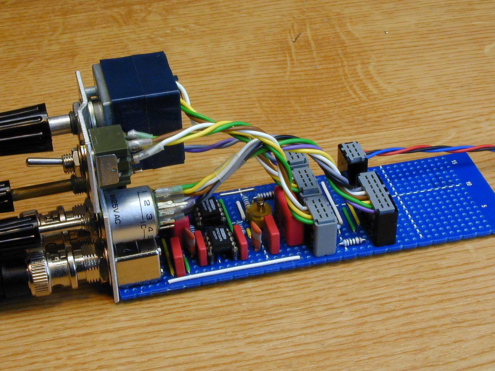
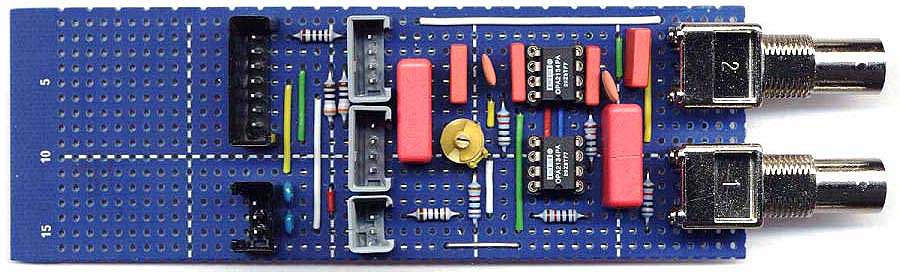
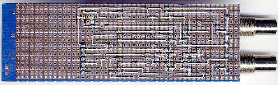
My favourite way is to use a special kind of square pad board (Vero) and to spend a lot of time designing the layout and its implementation because I very much enjoy the aesthetic aspects of electronics. Perhaps somebody else feels like me.
| Last update: October 13th, 2015 | Questions? Suggestions? Email Me! | Uwe Beis |