| |
|
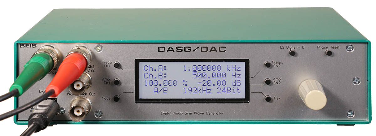
DASG - Digital Audio Sine Wave Generator
| |
|
DASG - Digital Audio Sine Wave Generator
During my life I designed a lot of test equipment just for myself, but none of them was as useful and became as indispensable as this device. I am convinced that everybody who deals with really precise (bit-precise) digital audio signals resp. signal processing never would want to forego this device once he learned to know it. I would love to build it in series, but my marketing department consists of nothing but this article - and that's by far too little for the few high-precision digital audio designers who probably would love the DASG as I do.
The original idea to build the DASG arose from the question how to generate sine values resp. a variable and precise sine wave digitally. I started it all when I heard about the CORDIC algorithm. This algorithm allows to realize virtually arbitrary precision with manageable effort.
12 VDC, 500 mA max.
| • | Frequency Ch. A | 0 - 95.999999 kHz in steps of 1 mHz | ||
| • | Frequency Ch. B | 0 - 95.999999 kHz in steps of 1 mHz or Same as Ch. A with phase shift 0 - 345° in steps of 15° | ||
| • | Amplitude Ch. A | 0 - -140.00 dB in steps of 0.01 dB or 0 - 100.000% in steps of 0.001% | ||
| • | Amplitude Ch. B | 0 - -140.00 dB in steps of 0.01 dB or 0 - 100.000% in steps of 0.001% or Same as Ch. A | ||
| • | Output (L/R) Mapping | A/B, B/A, A/A, B/B, A/A+B, A/A×B, A+B/A+B, A×B/A×B | ||
| • | Sample Rate (kHz) | 8, 12, 16, 24, 32, 44.1, 48, 64, 88.2, 96, 176.4, 192 | ||
| • | No. of Active Bits | 2 - 24 (rounded to no. of active bits, remaining bits set to zero) |
 Pushbuttons for
Rotary encoder (incremental switch) for numeric values with push-function for digit resp. item selection.
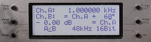
The photo on the right, compared to the photo at the beginning, shows a couple of alternative settings.
With the DASG I could verify that my digital parametric equalizer DPEq8 processes the audio signals mathematically exactly.
For the DPLCM-VFD I could check whether all displayed values are mathematically exact and that the clipping-indicator (at least 3 full-scale samples in series) works as intended.
For tests and verification of another audio measuring device that I designed, the LM 1128 and the LM 128P, I needed a precise source, too. Not only the measured values, but also the frequency response and again the correct clipping display mattered here.
For the USB-interface DA2USB in conjunction with different audio recording programs I used the DASG to check whether really a bit-precise recording at all sample rates took place. And I was deeply disappointed that, in contrast to my expectation, that was not the case. But that's another story and I hope that my discussions with the Audacity crew about the solution that we found will be adopted in the next Audacity version 2.1.3.
Though the DASG is primarily intended as a generator for digital signals, its ability to generate simultaneously two independent analog signals is often helpful in stereo applications.
These are examples with projects that I presented on my website only. Of course I spent my time with many more projects and of course I used the DASG in many of these cases.
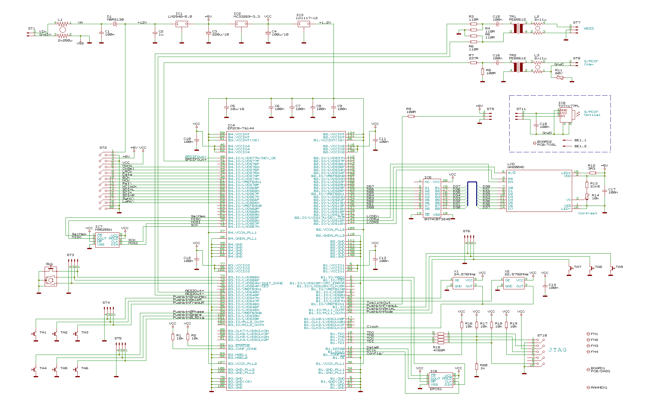
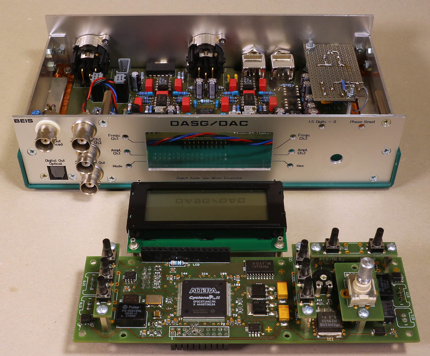 The hardware is basically a quite small Altera Cyclone II FPGA (EP2C5). I used no internal processor, i.e., all is written in VHDL, there is no C or assembler code. You can find the circuit diagram here.
Of course, internally the DASG operates with two independent NCOs (numerically controlled oscillators), counting over 11⅓ BCD digits (45 bit), one for each channel. These NCOs represent the current phase angles and allow an internal resolution of 1 µHz and a maximum frequency of ~192 kHz. BCD arithmetics turned out to be more uncomplicated in the design because I used no processor to do binary/BCD conversions.
The sine wave conversion using the CORDIC algorithm operates with 32 bit accumulation registers. This and an internal multi-bit operation guarantees that the resulting rounding noise is by far below the aimed audio signal precision of 24 bit.
Settings are stored in an EEPROM so that after restart all settings are unchanged.
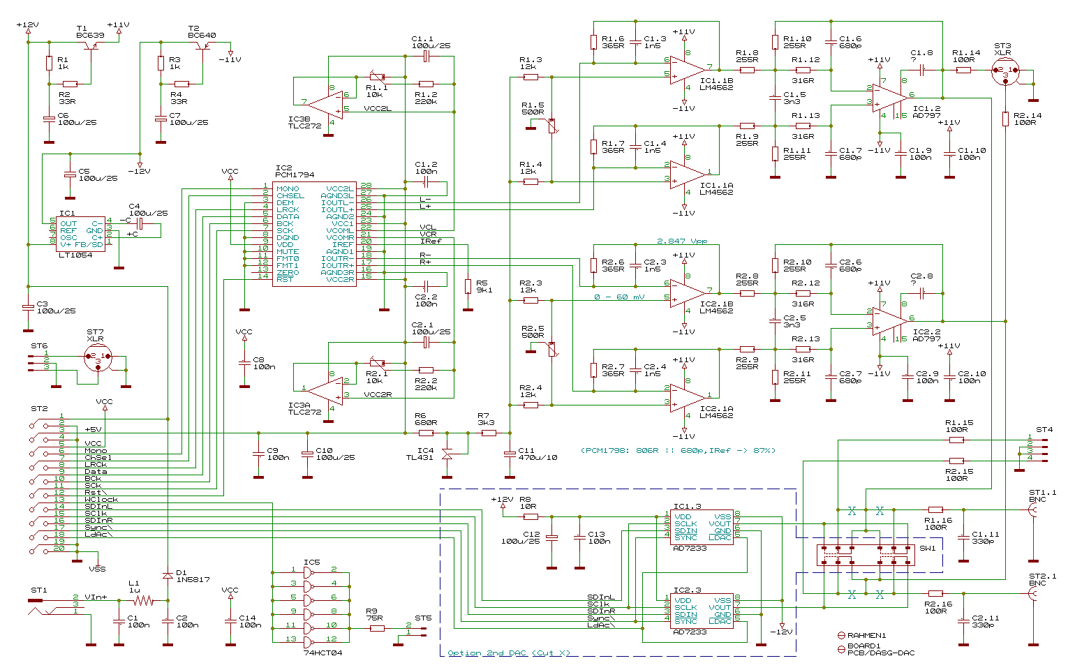
I provided two dual channel DACs, see here. The first is a high precision, low-noise audio DAC based on the TI PCM1794. The output amplitude of 2 VRMS and its offset can be precisely adjusted. The second is a normal industrial DAC (2 x AD7233) without low-pass filtering, intended more to make the digitally generated values visible on an oscilloscope. I thought it to be a nice idea for e.g. educational purposes, but actually I never used it - in contrast to the other features of the DASG.
Would I redesign the DASG, I would change only few things: As I often change the sample rate, this should be the first item of the Mode settings. The pushbuttons are quite small. Pressing while turning the rotary encoder is slightly awkward as it takes both hands due to the device's low weight. Finally, the analog part should be revised.
The image on the right shows the DASG disassembled with the digital board and its control elements in front, the LCD and the analog section inside the enclosure. Click to enlarge the image.
This seems to be a trivial, almost needless question. But when I had to think about the exact scaling of digital audio signals I came to a different conclusion.
In the AES3 standard you'll find stated:
Representation is linear in 2’s complement binary form. Positive numbers correspond to positive analog voltages at the input of the analog-to-digital converter (ADC).
This seems to be obvious. But keep in mind: An ADC, particularly an audio ADC with a very high resolution, never(!) will have to convert an ideally zero volt input signal. Analog signals never have an exact level. Additionally, all analog devices produce noise, so that an analog signal that we would understand to be 0.0 V will always just vary around 0.0 V. In other words, it will be either negative or positive and only its mean value will be zero (or, to be more precise: Closer to zero than the momentary values).
In practice, when this AES3 statement is implemented strictly, with an analog input voltage of 0.0 V the ADC's digital output will always change between the smallest positive number (= 0) and the smallest negative number (= -1).
Conclusion: When this AES3 statement is implemented strictly, for an average analog value of 0.0 V the average digital value will be -0.5. Moreover, because I expect from a DAC to output 0.0 V when the digital input is 0, in case of an ADC input voltage of 0.0 V this DAC would output averagely a slightly negative voltage.
Now you may understand my doubts and thoughts about this matter. Of course, in practice this does not matter at all, but when you design a high precision signal generator where errors far below one LSBit are aimed, it matters a lot!
So once again: How should digital zero be defined? Simply: Any average analog input voltage of 0.0 V should be converted to an average digital value of 0. This seems to be trivial, too, but it contradicts the AES3 statement. Anyway, I regard my definition much more logical and that's why I follow it in the DASG design.
Now lets play a little with it: Small analog values, e.g. a sine wave that is smaller than ±½ quantization interval, will hence be converted to digital zero. When this sine wave slightly exceeds ±½ quantization interval, it will be converted mostly to 0, positive peaks to +1 and negative peaks to -1. To large values applies: The most positive values of an n-bit signed binary number is 2n-1 and the most negative value is -2n (e.g. 16 bit: 0x7FFF = +32767 and 0x8000 = -32768). According to my definition I would allow a symmetrical range of values between 2n-1 and -2n-1 only, e.g. in case of 16 bit: 0x7FFF and 0x8001. This is how the DASG's signal range is defined. The most negative value is not used.
Another thought: When e.g. a small 24 bit digital signal, let's say between +10 and -10, is reformatted to a 16 bit signal, the removed LSBs must be use for rounding before truncation. Example:
Wrong: -10dec = 0xFFFFF6 would be truncated to 0xFFFF = -1dec, while +10dec = 0x00000A would be truncated to 0x0000 = 0dec. The original average value of 0 would be lost. That is why rounding before truncation is necessary:
Correct: -10dec = 0xFFFFF6 + 0x000080 = 0x000076 will be truncated to 0x0000 = 0dec, while +10dec = 0x00000A+ 0x000080 = 0x00008A, will be truncated to 0x0000 = 0dec, too. Perfect.
This is how the DASG works. Internally, always 32 bit values between 0x80000001 and 0x7FFFFFFF are calculated, afterwards rounded for the the selected the number of active bits (between 2 and 24) and finally all inactive bits are replaced by 0 (resp. truncated). From this it follows that the transmitted full-scale peak values for different numbers of active bits are:
| No. of Bits | Min. Neg. | Max. Pos. | Decimal |
| 2 | 0xC00000 | 0x400000 | ±1 × 222 |
| 3 | 0xB00000 | 0x600000 | ±3 × 221 |
| 4 | 0x900000 | 0x700000 | ±7 × 220 |
| ... | ... | ... | ... |
| 15 | 0x800200 | 0x7FFE00 | ±16383 × 29 |
| 16 | 0x800100 | 0x7FFF00 | ±32767 × 28 |
| 17 | 0x800080 | 0x7FFF80 | ±65535 × 27 |
| ... | ... | ... | ... |
| 22 | 0x800004 | 0x7FFFFD | ±2097151 × 4 |
| 23 | 0x800002 | 0x7FFFFE | ±4194303 × 2 |
| 24 | 0x800001 | 0x7FFFFF | ±8388607 |
Note that these values, shown here as integers, should be interpreted as fixed point numbers. Technically, the first transmitted bit is always the most significant bit (MSB), which is the sign bit.
The following screenshot of 1 kHz signals from the DASG, recorded with Audacity and my DA2USB, shows the effect of different numbers of active bits:
 |
2 bits, 3 levels: The signal spans +0x4000 to -0x4000, ~1/2 of the full scale of ±0x7FFF | |
| 3 bits, 7 levels: The signal spans +0x6000 to -0x6000, ~3/4 of the full scale of ±0x7FFF | ||
| 4 bits, 15 levels: The signal spans +0x7000 to -0x7000, ~7/8 of the full scale of ±0x7FFF | ||
| 5 bits, 31 levels: The signal spans +0x7F80 to -0x7800, ~15/16 of the full scale of ±0x7FFF | ||
| 8 bits, 255 levels: The signal spans +0x7F00 to -0x7F00, ~127/128 of the full scale of ±0x7FFF | ||
| 16 bits, 65535 levels: The signal spans +0x7FFF to -0x7FFF: Full scale |
In practice, due to its anti-aliasing low-pass filter, at the output of a DAC the analog signal may exhibit ringing. The screenshot below shows how the 2 bit signal above, where this effect is extreme, looks like at a DAC's output:
Some signal samples generated by the DASG.
Ch. A, Ch. B: The DASG's signal settings
CH1, CH2: The DASG's mapped outputs 1 & 2 displayed on the oscilloscope's traces 1 & 2
Screenshot above:
Ch. A = Ch. B = 100 Hz, 100% FS
Ch. B phase = +45°
CH1 = Ch. A
CH2 = Ch. B
Screenshot above:
Ch. A = 100 Hz, 50% FS
Ch. B = 1 kHz, 50% FS
CH1 = Ch. A
CH2 = Ch. A + Ch. B
Screenshot above:
Ch. A = 100 Hz, 100% FS
Ch. B = 1 kHz, 100% FS, phase = 0°
CH1 = Ch. A
CH2 = Ch. A × Ch. B
Screenshot above:
Ch. A = 100 Hz, 100% FS
Ch. B = 300 Hz, 40% FS, phase = 0°
CH1 = Ch. A
CH2 = Ch. A + Ch. B
Screenshot above:
Ch. A = CH1 = 90.0 kHz, 100% FS
Ch. B = CH2 = 94.5 kHz, 100% FS
Sample Rate = 192 kHz
It is obvious that very close to the Nyquist frequency of 96 kHz the DAC's anti-aliasing filter is not able to separate the base frequency (94.5 kHz) from its mirror frequency (97.5 kHz) correctly any more. A 3 kHz (333 µs) beat arises.
| Last update: August 5th, 2016 | Questions? Suggestions? Mail Me! | Uwe Beis |