|
|
|
|
|
|
This RF-circuit is operating at 7.68 MHz and 48 V phantom power supplied. It is tested with a large diaphragm cardioid capsule from Ralf Falk, who himself is designing a LF tube microphone and with a small diaphragm capsule from a Sennheiser MKH415. (Do not mix up: "RF" stands for "Radio-Frequency", not for "Ralf Falk"!)
Lots of experiments, gathered experiences and improvements during the development - with quite satisfactory results, to my point of view.
There are two basic ways to implement an RF condenser microphone.
- Either the capsule's capacitance is part of an oscillator's resonant circuit, so that the oscillator's frequency is modulated with the audio frequency and can be demodulated with a usual frequency demodulator or discriminator.
- Or a fixed oscillator generates a fixed frequency and the capsule's capacitance is part of the frequency demodulator, so that with the audio frequency it detunes the demodulator and thus produces the audio signal.
My circuit is of the latter type. "My circuit" - no, it is not invented by me. It is very similar to the one of the Sennheiser MKH-series introduced some 10 years ago (MKH406-P48, MKH416-P48 and so on). I believe this concept to be quite ingenious and I am convinced not to have any chance to surpass it, so I made mine a little different only.
The oscillator runs with a crystal of 7.68 MHz. Other frequencies would do, too, if they were within the tuning range of the succeeding inductors. The oscillator's low voltage output at pins 2, 1 and 6 has one or two windings resp., and with J4 to J6 it is possible to test the effects of different input voltages to the FM-demodulator.
The demodulator circuit (C5 - C7 and L2 and, most important, the capsule) is fed by C5 with a 90° phase shifted reference signal, which is phase shifted another +/-90° by L2 and CCapsule. Depending on the overall phase shift the demodulator's output voltage across C6 and C7 is either positive, zero or negative. J1 and J2 allow to select between different capsule capacitances. Opening J3 allows to introduce voltages or capacitances for further experiments.
For both, the oscillator and the demodulator inductor, I went over to use high quality ferrite cores (Epcos RM5, K1, AL25) after experiencing poorer results with cheaper cores.
The AF signal across C8 is amplified by T2, T3 and T4 to become a low-impedance output signal. By means of C9 - C11 and R5, low and high frequencies can be amplified additionally. This is required in case of a capsule with a non-linear frequency response, like the one of the MKH415 I have. With C11 of e. g. a couple of µF and without C9, C10 and R5 a linear frequency response is achieved.
Usual push-pull power output stages have a constant current
consumption over a wide range of supply voltage. In contrast to
that, this output stage, formed by T3 and T4,
has a constant voltage consumption over a wide range of supply
current, i. e., it behaves more like a Zener diode. Not really
easy to understand is why the output stage, though it is an unbalanced
concept, produces a balanced output signal. The key to understand
this is that it's supply practically (by the constant current
source and the transformers L1 and L2) is
floating as if the output amplifier was supplied by a separate
battery.
The whole circuit is not, as usual, fed by a constant voltage with all sub circuits connected in parallel to that supply. It is rather fed by a constant current of 2 mA with all sub circuits connected in series to that supply. The constant current source is formed by T5 and T6. Practically I experienced a more linear demodulator characteristic by omitting ZD1.


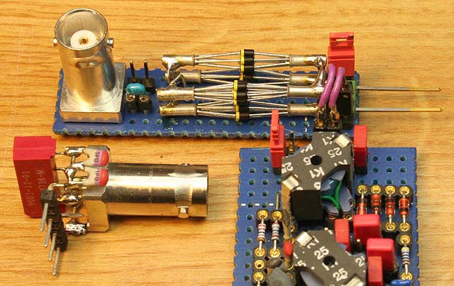
For testing and optimization of this circuit I of course used several usual instruments. Very helpful were these two capsule simulators: One is a small capacity switcher, where the capacity is switched by a relay, and the other one is a continuously tunable capacitor build out of 28 Varicap-diodes. Though I used a lot of diodes, this circuit is not too linear, but it helps very much to optimize e. g. the dynamic range of the demodulator or to determine the overall frequency response of the circuit.
The sensitivity of my circuit is slightly less than the original MKH415 I have, i. e., it produces a little bit more noise compared to the same input signal (= capacitance change). Also, the MKH415 has a wider dynamic range, i. e., its maximum output voltage is higher. But what would you expect, when a "newbie" within a couple of days tries to challenge professionals with years of experience?
This project is experimental. Should you work on something where it might be interesting, i. e. on microphones, or should it be interesting for you anyhow else, I'd appreciate your feed-back. So you are very welcome to email me!
| Last update: October 13th, 2015 |

|
Uwe Beis |