AD24QS -
Audio Analog to Digital Converter
24 Bit / 192 kHz (now updated to Revision 4)
and
AD-IOA -
Input Output Extension Module with Microphone Amplifiers
Read also about the
New and quite unique DA2USB - Digital Audio to USB Interface (not only for the AD24QS)
Contents
General Description
Circuit Description
AD-IOA
The DIY Section
Options
Circuit diagram AD24QS as GIF-file or PDF-file
Circuit diagram AD-IOA as GIF-file or PDF-file
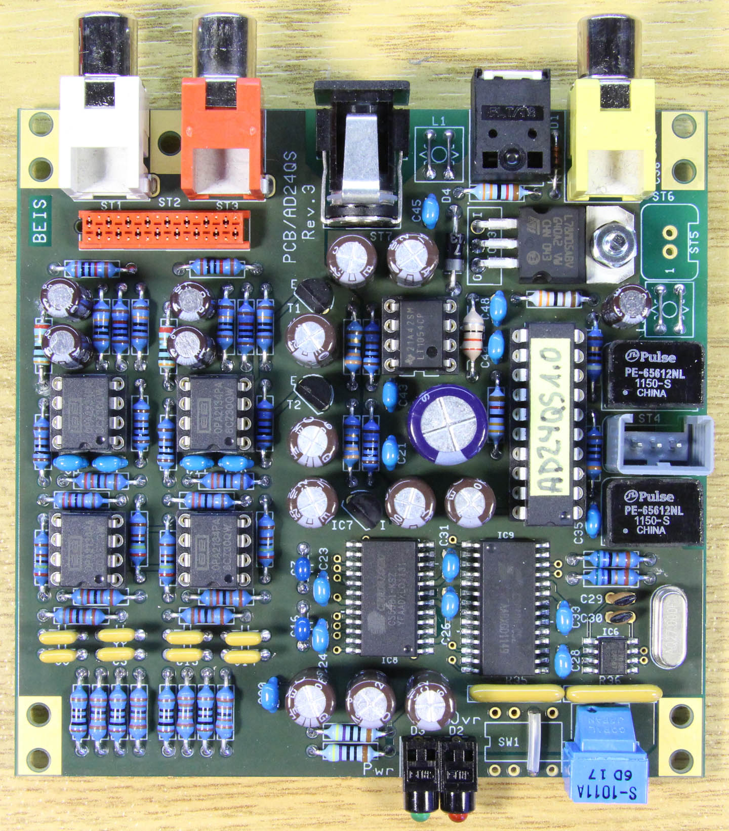
Assembly drawing AD24QS-K, revision 3, indicating the component names and the component types or values
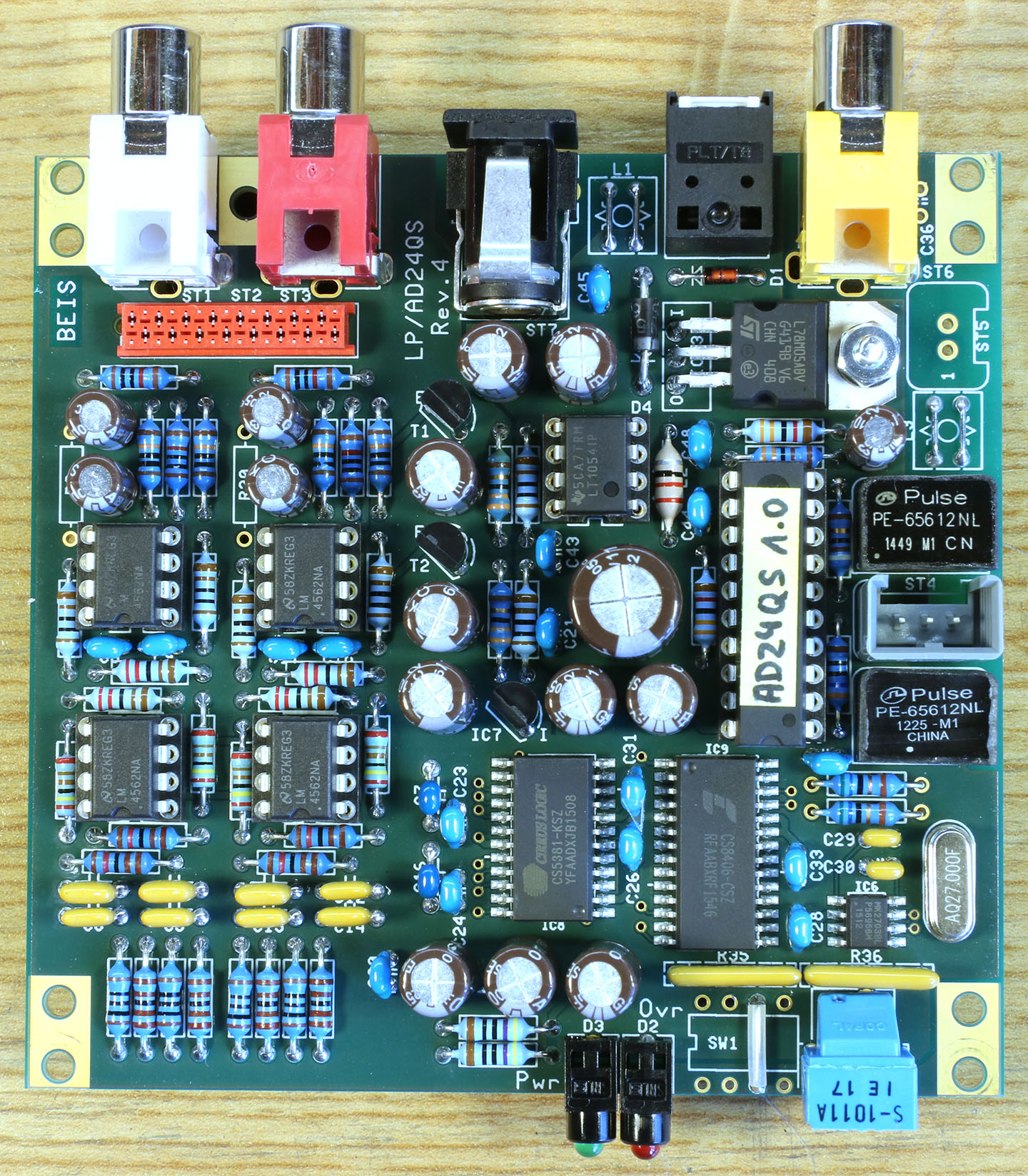
Assembly drawing AD24QS-K, revision 4, indicating the component names and the component types or values
Assembly drawing AD-IOA indicating the component names and the component types or values
Enclosures and Front Panels
Bill of Material AD24QS
Bill of Material AD-IOA
How to order
General Description
The AD24QS is a high quality Audio Analog to Digital Converter
available as kit for DIY (Do It Yourself). It features:
|
Sample Rates |
|
10 different ones, 16 - 192 kHz |
|
Analog Inputs |
|
On-board Stereo (RCA), 10 kΩ
Option: External XLR balanced, 20 kΩ |
|
Input Sensititivity @ 100% FS |
|
2 VRMS
Others or adjustable gain as option |
Dynamic Range
20 Hz - 20 kHz |
|
109 dB unweighted, typically
111 dB A-weighted typically
Option "Flagship" chip-set: 115 (117) dB approx. |
|
THD |
|
typ. -120 dB @ -6 dB FS |
|
Digital Audio Outputs |
|
1 x on-board optical (Toslink, up to 96 kHz only)
1 x on-board coaxial (RCA), 75 Ω
Option: External AES3 XLR balanced, 110 Ω |
|
Latency |
|
192 kHz: 46 µs
96 kHz: 126 µs
48 kHz: 310 µs
44.1 kHz: 275 µs (yes, less than @ 48 kHz) |
|
Frequency Response |
|
2 Hz - SR / 2 @ -3 dB
Except 192 kHz SR: 3 Hz - 73 kHz @ -3 dB |
|
Power Supply Rejection Ratio |
|
approx. 100 dB @ 100 Hz |
|
Power Supply |
|
Standard version: 12 V DC, 180 mA approx.
Option "Flagship" chip-set: 12 V DC, 210 mA
approx. |
|
Board Size |
|
91.44 mm x 88.27 mm (3.6" x 3.475") |
|
Mechanical Drawing |
|
GIF file or PDF
file |
|
|
|
The data above is measured at my samples and cannot be guaranteed,
of course.
Note: From revision 4 on only the "Flagship" version is still available. The difference between revisions 3 and 4 is a slight change in the layout.
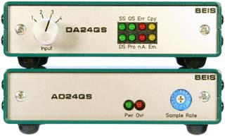
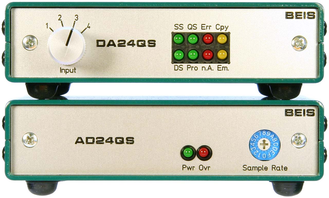
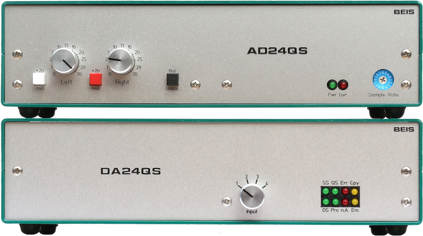
Sample Rates
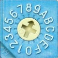 The ADC is capable
of 10 different sample rates up to 192 kHz, set with the
switch on the ADC's front:
The ADC is capable
of 10 different sample rates up to 192 kHz, set with the
switch on the ADC's front:
|
Setting |
|
Sample Rate (kHz) |
|
Format |
|
Copyright |
|
0 |
|
16 |
|
Professional |
|
- |
|
1 |
|
22.05 |
|
Professional |
|
- |
|
2 |
|
24 |
|
Professional |
|
- |
|
3 |
|
32 |
|
Professional |
|
- |
|
4 |
|
44.1 |
|
Professional |
|
- |
|
5 |
|
48 |
|
Professional |
|
- |
|
6 |
|
64 |
|
Professional |
|
- |
|
7 |
|
88.2 |
|
Professional |
|
- |
|
8 |
|
96 |
|
Professional |
|
- |
|
9 |
|
192 |
|
Professional |
|
- |
|
A |
|
44.1 |
|
Consumer |
|
Not asserted |
|
B |
|
44.1 |
|
Consumer |
|
Asserted, original version |
|
C |
|
44.1 |
|
Consumer |
|
Asserted, copied version |
|
D |
|
48 |
|
Consumer |
|
Not asserted |
|
E |
|
48 |
|
Consumer |
|
Asserted, original version |
|
F |
|
48 |
|
Consumer |
|
Asserted, copied version |
The first 10 sample rates, with the digital audio signal indicated
as "Professional Format", are selected in positions
1 - 9.
Positions A - F are indicated as "Consumer Format",
where you can select 44.1 kHz or 48 kHz only, but each
with the options "no copyright asserted", "copyright
asserted, original version" and "copyright asserted,
copied version". In Consumer Mode the ADC's category code
is "General" (00hex). Using a decimal encoding
switch would prevent access to the consumer format.
LEDs
A green "Power"-LED is provided. The red "Ovr"-LED
on the front lights up, when at least one of the channels is overdriven.
If both are overdriven, it is brighter.
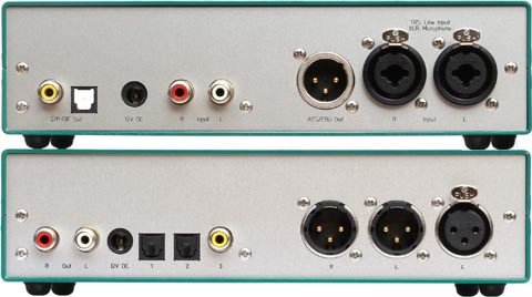
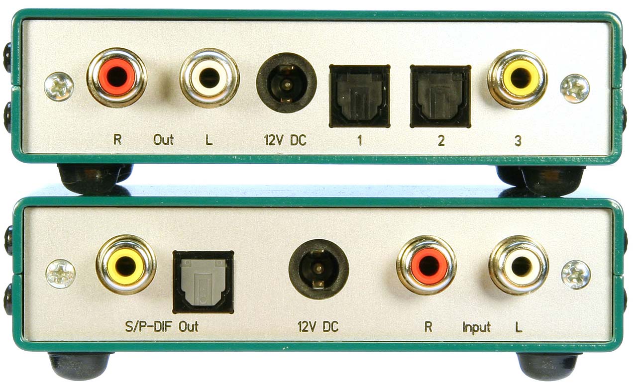
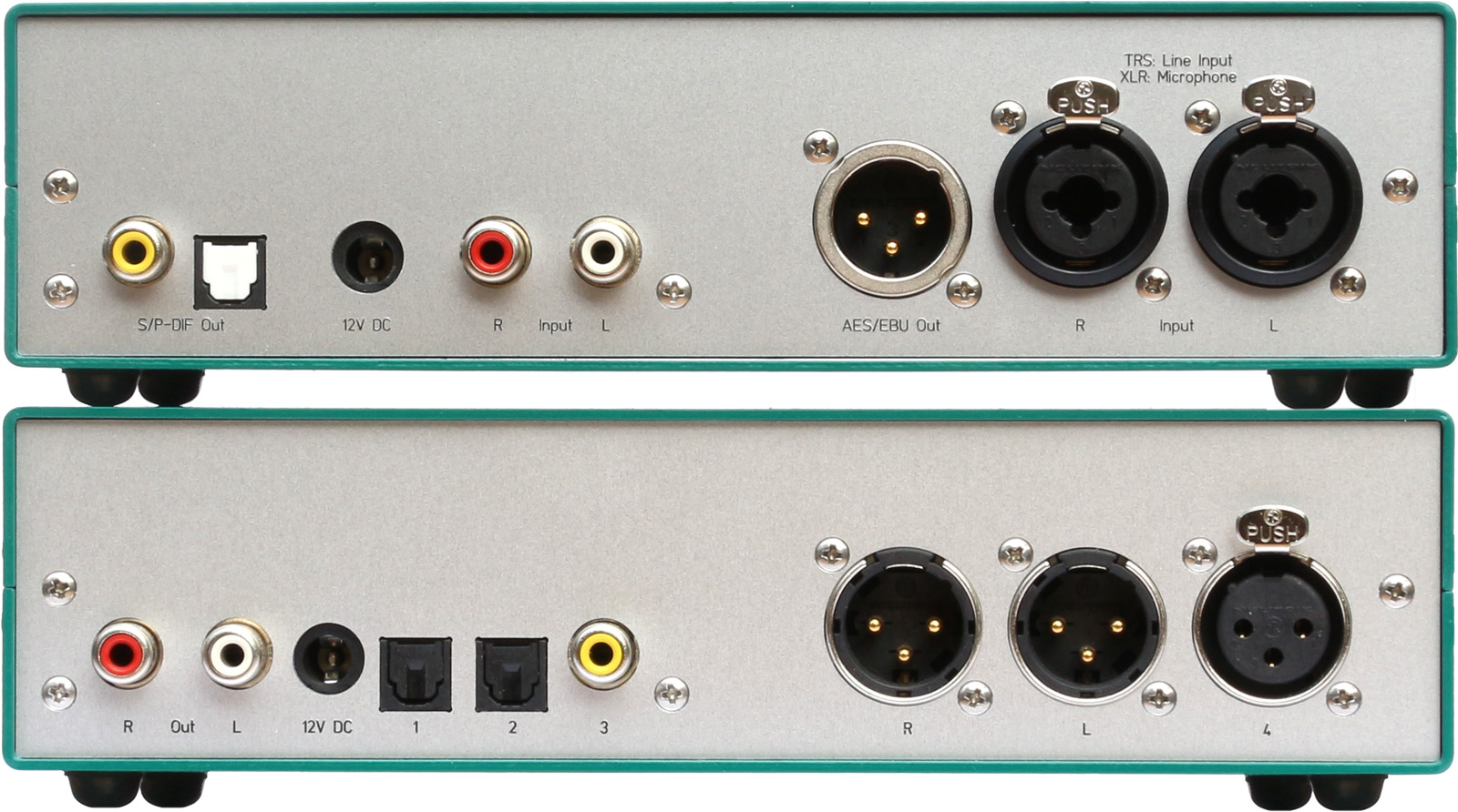
Analog Inputs
 All
connections are made on the rear. The analog, unbalanced RCA inputs
have a sensitivity matching the usual CD or DVD player output
level of 2 VRMS. As options, a gain switch can
easily be connected externally as well as balanced XLR inputs
and a selector switch between RCA and XLR inputs.
All
connections are made on the rear. The analog, unbalanced RCA inputs
have a sensitivity matching the usual CD or DVD player output
level of 2 VRMS. As options, a gain switch can
easily be connected externally as well as balanced XLR inputs
and a selector switch between RCA and XLR inputs.
Digital Audio Outputs
Both digital audio outputs, the optical and the unbalanced
RCA output, can be used simultaneously. The RCA output is galvanically
decoupled by a digital audio transformer. Also as an option, a
third, e.g. balanced (XLR- or AES3-) digital audio output with
its own digital audio transformer can be connected externally.
The optical output device (the obsolete TOTX177PL or its replacement
PLT133) is specified up to slightly more than 96 kHz only, though
it works on the workbench up to 192 kHz without any problems.
Anyhow, I do not recommend to use it for 192 kHz.
USB Interface: The DA2USB
I often was asked for a USB connection.
Now I can offer the DA2USB, a driverless USB interface for transferring digital audio signals into a PC with up to 192 kHz / 24 bit. Thus it is a perfect completion for the ADCs. This is a separate module and kit. Read here about the DA2USB and how to combine it with the AD24QS
Input Levels and Other Technical Data
The preamplifiers are dimensioned for an input sensitivity
of 2 VRMS approx. at 100% FS, a usual level
e.g. for CD or DVD players.
When the balanced XLR input option is used, the input sensititvity
should be reduced to the standard studio level of +4 dBu
(1.23 VRMS) plus a reasonable headroom of e.g.
12 dB. I.e., 4.91 VRMS (+16 dBu) for
100% FS might be a good choice.
Meanwhile I offer the AD24QS in the "Flagship" version only, i.e., "Flagship" is no longer an option but the new standard version. Compared to the former standard version, it consists of a significantly
more expensive ADC-IC which the manufacturer calls his "Flagship"
and better (and more expensive) op-amps. An approximately 6 dB
higher dynamic range than with the standard chip-set is achieved.
For more measurements I made on the previous prototypes read
the corresponding article
about the AD2496.
Power Supply
The nominal power supply is 12 V DC, but up to 15 V
are allowed. The current consumption is about 180 mA for
the standard and 210 mA for the "Flagship" version.
I use regulated power supplies even though unregulated ones
are ok, too. Due to the ADCs' high power supply rejection ratio
only very little hum from unregulated power supplies remains in
the output signal so that the ADCs' dynamic range is not decreased
noticeably (unweighted measurements). BTW, I measured with a full-wave
rectified 9 V transformer (i.e., without buffer capacitor)
the same dynamic range as with a regulated power supply. Even
in the worst case with a bare 9 V AC supply (which is possible,
too) and the "Flagship" chip-set the dynamic range was
decreased by less than 1 dB. Only in the spectrum you can
observe the effect of an unregulated power supply.
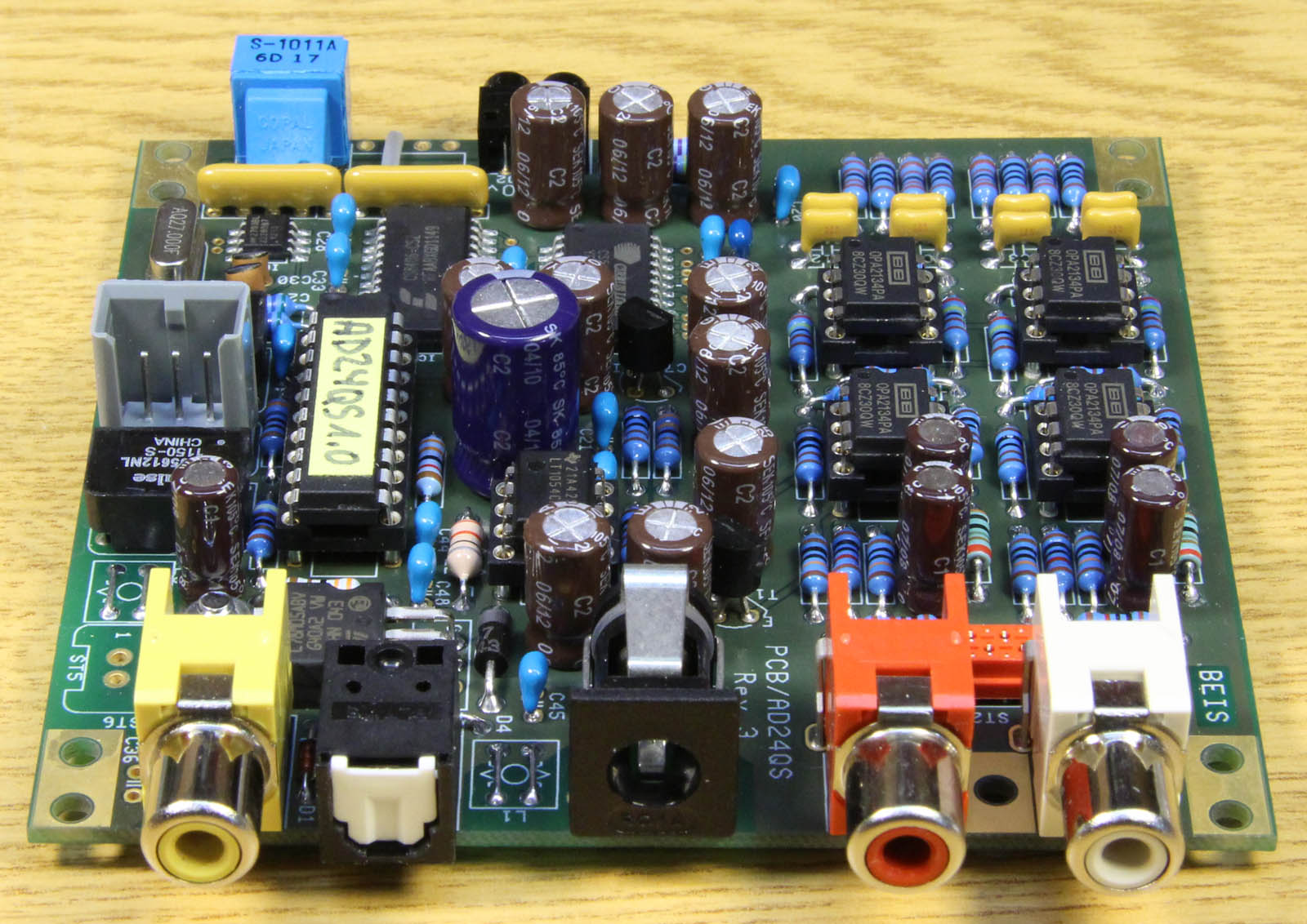
Circuit Description
 For
the current circuit diagram of the AD24QS, have a look either
at the GIF-file or the PDF-file.
For
the current circuit diagram of the AD24QS, have a look either
at the GIF-file or the PDF-file.
Analog Inputs
The analog stages up to and including the ADC-IC's input are
designed fully balanced, though, in the basic kit version, the
input jacks are unbalanced only. The first stage serves as input
buffer but an additional amplification can be introduced there,
too. The second stage is a balancing 2nd order low-pass
Butterworth filter with a corner frequency of 190 kHz approx..
The AD24QS can be equipped with external professional, balanced
audio inputs (XLR) and also with an external switch to select
between the on-board unbalanced RCA or the external XLR inputs.
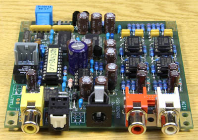
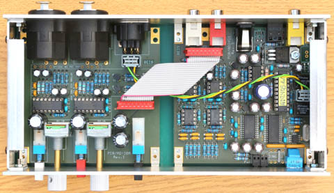
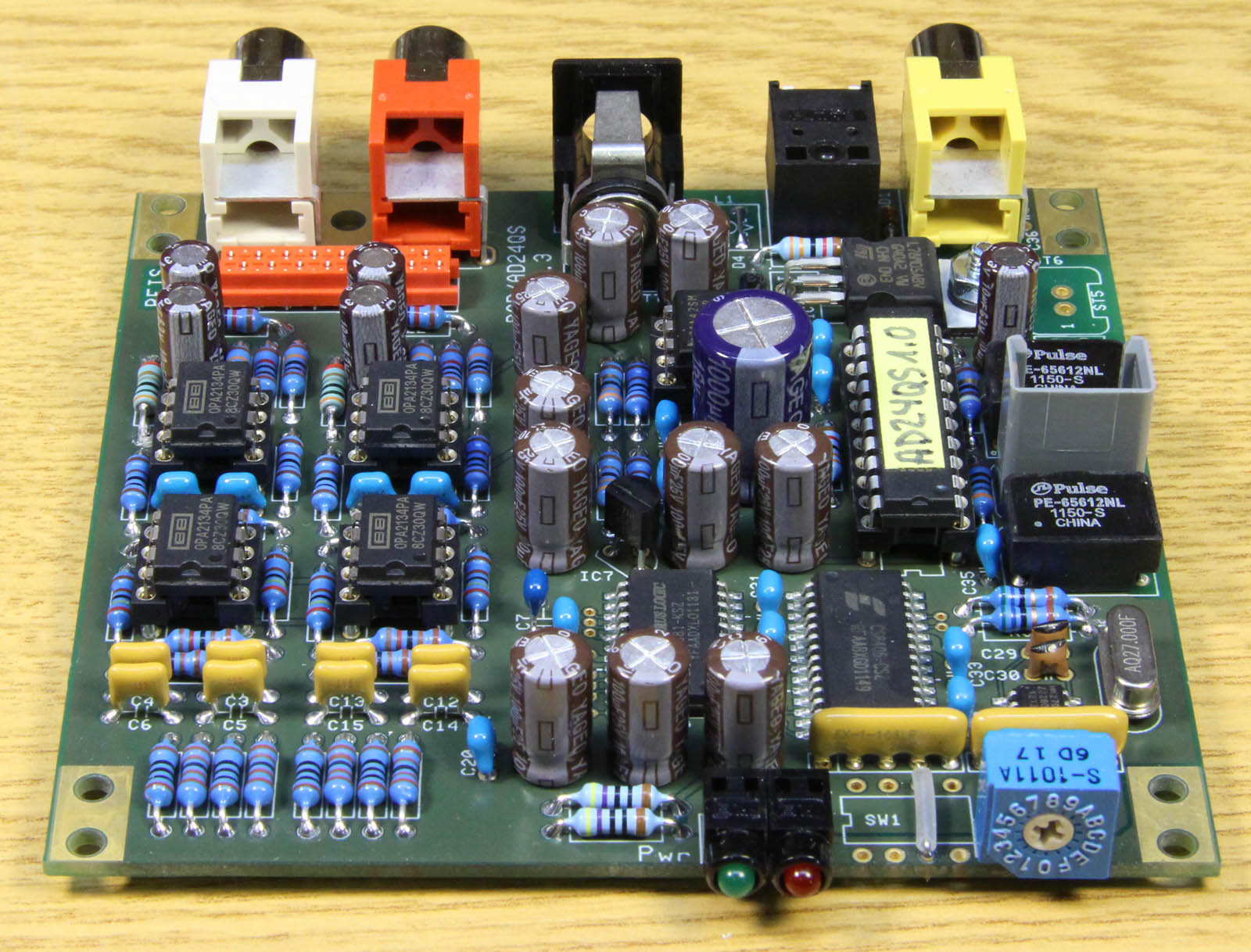
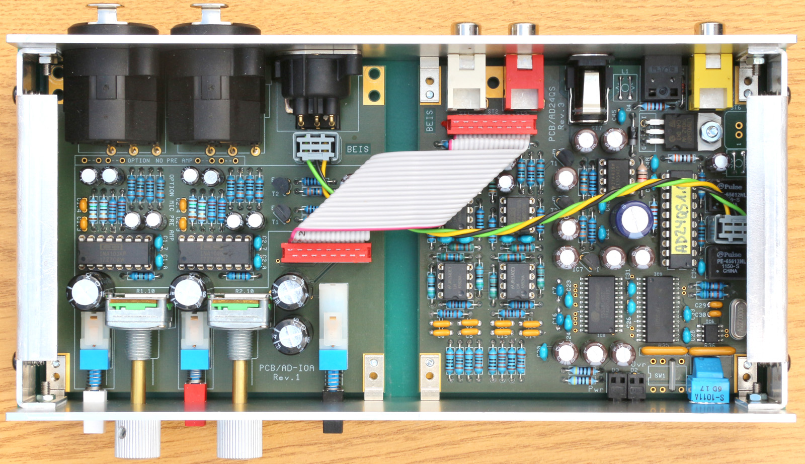
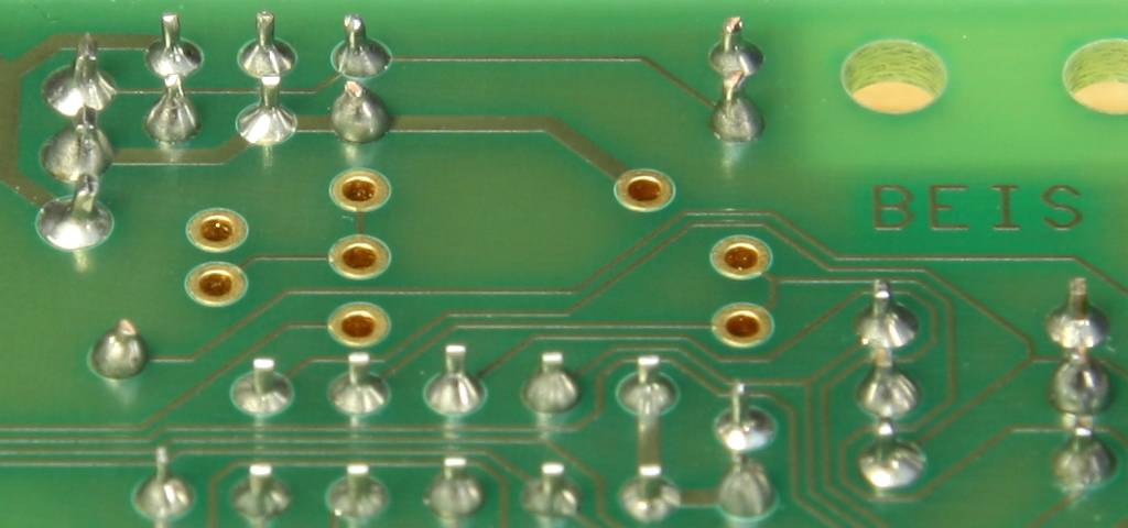
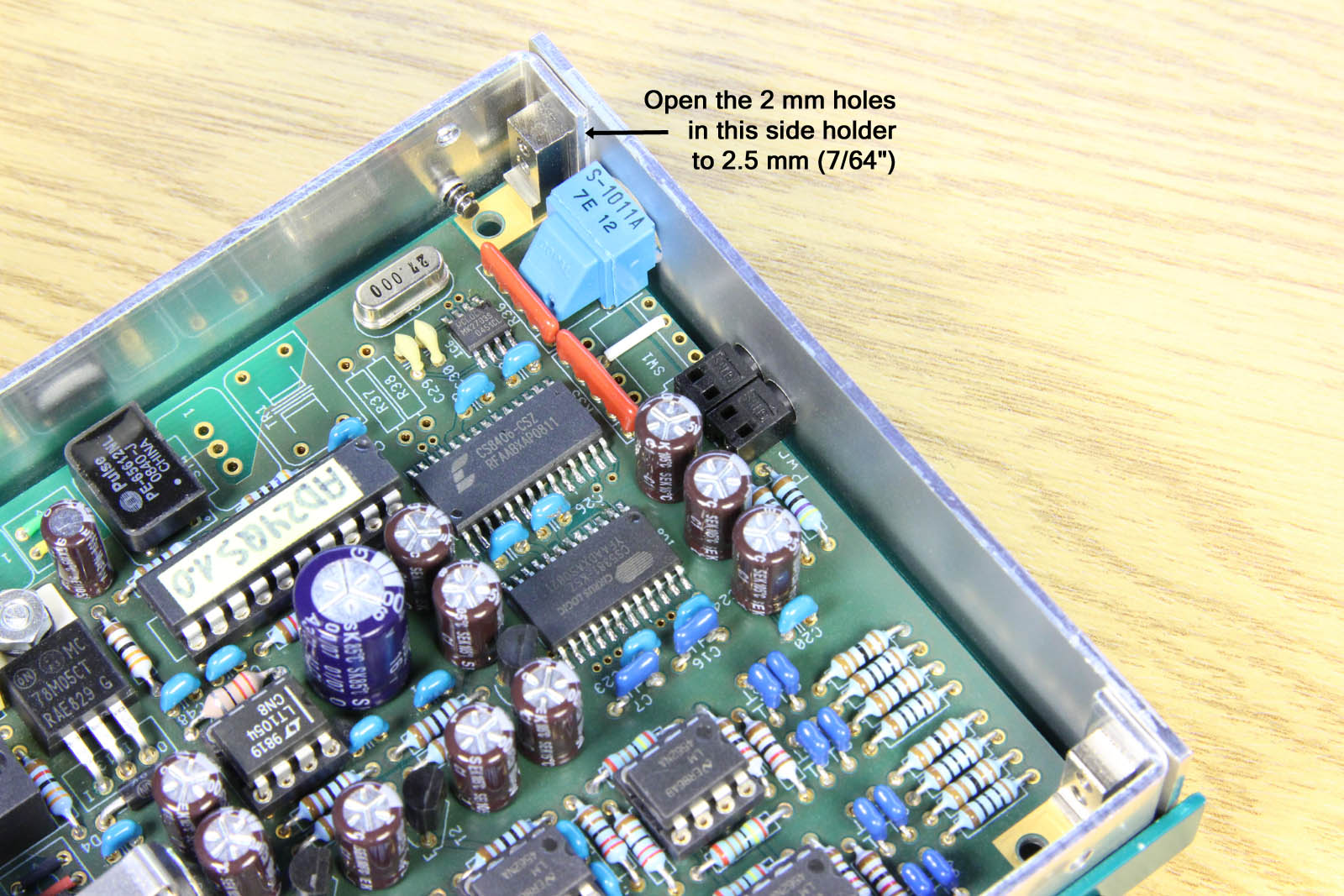
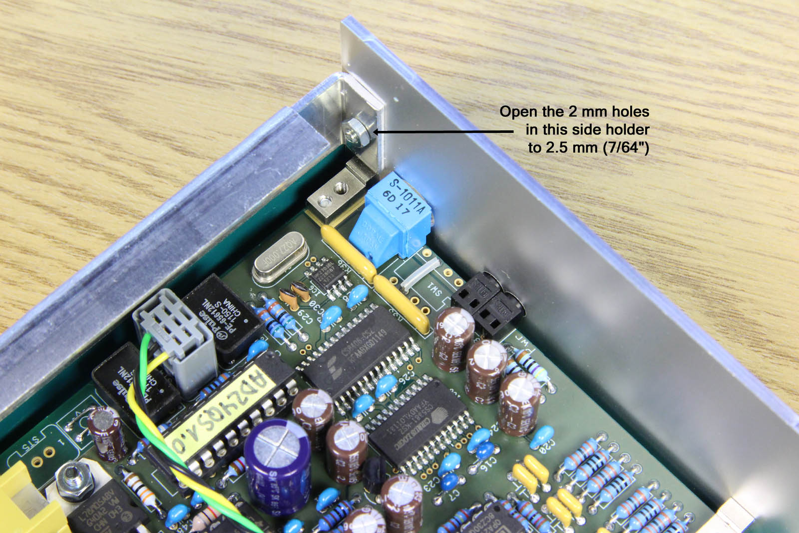
Extension features: For the balanced inputs and the adjustable
gain option an additional connector can be placed. This Micro-Match
(or compatible) connector does not only carry the audio and gain
adjustment signals but the power supply, too. On the photo you
can see the position for this Micro-Match connector, but it is
not populated there. The AD-IOA,
an input/output extension module, takes ample advantage of all
these features.
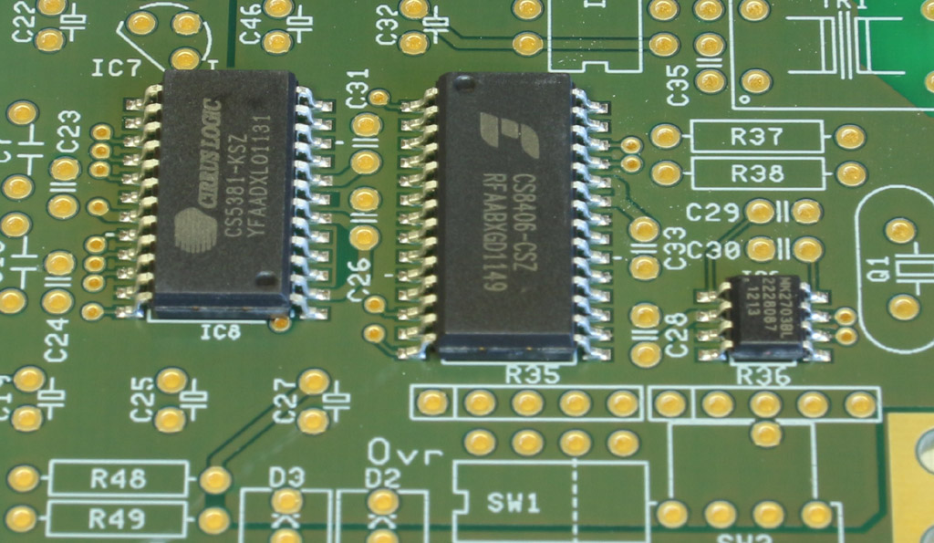
ADC
The Cirrus Logic CS5361
is a high quality 114 dB delta sigma A/D converter. The reference
supply is a simple 78L05A, but there is no reason for concerns
about its noise as reference voltage noise is very well filtered
by the ADC's external filter components. From revision 4 on I offer the AD24QS with the even better and significantly more expensive 120 dB
ADC CS5381.
Clock
The clock generation is done by an MK2703S, a "PLL Audio
Clock Synthesizer", which is an oscillator and PLL circuit
for the 44.1 kHz and 48 kHz based oscillator frequencies
derived from a single 27 MHz crystal.
S/PDIF Transmitter
I use a Cirrus Logic CS8406
"192 kHz Digital Audio Interface Transmitter" in hardware
mode. The hardware mode provides enough functionality, i.e., signal
inputs for control, for my goals. Three digital audio outputs
can be connected to the S/PDIF transmitter's outputs: One optical
output device (Toslink TOTX177PL or compatibel), one unbalanced electrical output
(0.5 VPP @ 75 Ω terminated). Moreover,
the AD24QS can be equipped externally with a professional digital
audio output, either balanced (XLR, AES3, 2 VPP
@ 75 Ω terminated) or unbalanced (BNC, AES-3id, 1 VPP
@ 75 Ω terminated). The decoupling transformer and
the termination resistors are provided on board.
The optical output device (TOTX177PL resp. PLT133/T8) is specified up to slightly
more than 96 kHz only, though it works on the workbench up to
192 kHz. Anyhow, I do not recommend to use it for 192 kHz.
At the end of 2011 during a great flood in Thailand Toshiba,
the manufacturer of the Toslink devices, lost all of its Toslink
audio components production equipment and decided not rebuild
the facility and not to resume the production. Since then only
remainders of these components are available world wide. There
are other manufacturers left but for me it seemed more or less
impossible to get parts from them in the small quantities I needed.
Finally I was lucky
with fully compatible parts from Everlight. The TOTX177PL, which
is still mentioned in the documentation, is replaced by PLT133/T8
(and the TORX147PL in the DA24QS by PLR135/T8).
The digital audio transformer for the coaxial signal is not
specified for 192 kHz either, but when you have a look at
its frequency response or its pulse transmission characteristics
you understand why I unscrupulously use and recommend it. It would
be fine for even much, much higher frequencies than 192 kHz.
Control Logic
In order to achieve these many sample rates I had to introduce
a more complex logic than on the AD2496.
It is still a static circuitry, but too complex for one or two
logic gate ICs. So I was forced to use some kind of programmable
logic and chose a GAL16V8, the simplest, smallest and cheapest
one that is available (except that, in order to save power, I
recommend the slightly more expensive quarter power version GAL16V8Q or equivalent).
In kits, you'll get them programmed.
Power supply
The nominal supply voltage for the device is 12 V, but
up to 15 V are allowed and it operates down to 10 V
or less. The power input is protected against polarity reversal
and buffered with an extra large, 1000 µF capacitor. The digital part of the AD24QS operates at 5 V. I use a
linear regulator, a standard 78M05 in a TO220-package, to regulate
the digital supply voltage.
Like in the DA24QS, the negative analog supply voltage is generated
by a DC-DC voltage inverter (LT1054,
up to 15 V / 100 mA) and both, the positive and the
negative analog supply voltages are smoothed by one low-pass emitter
follower each.
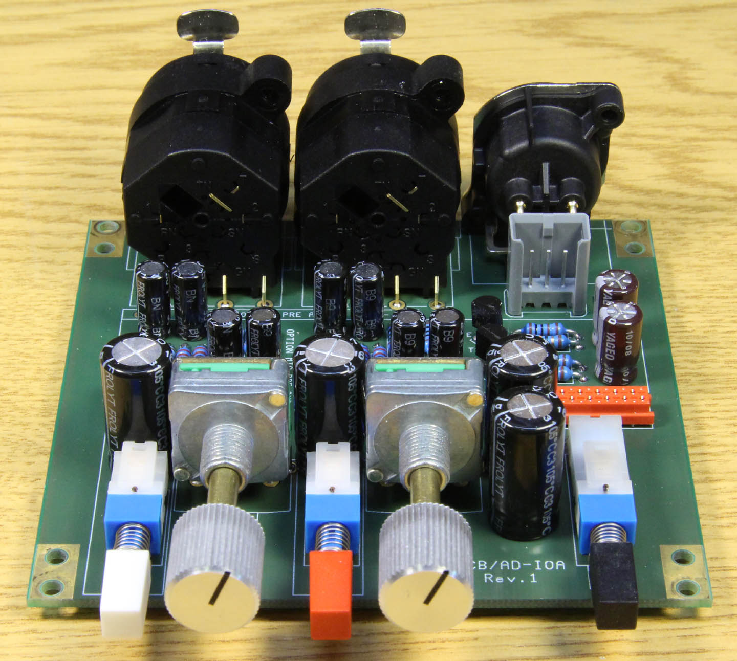
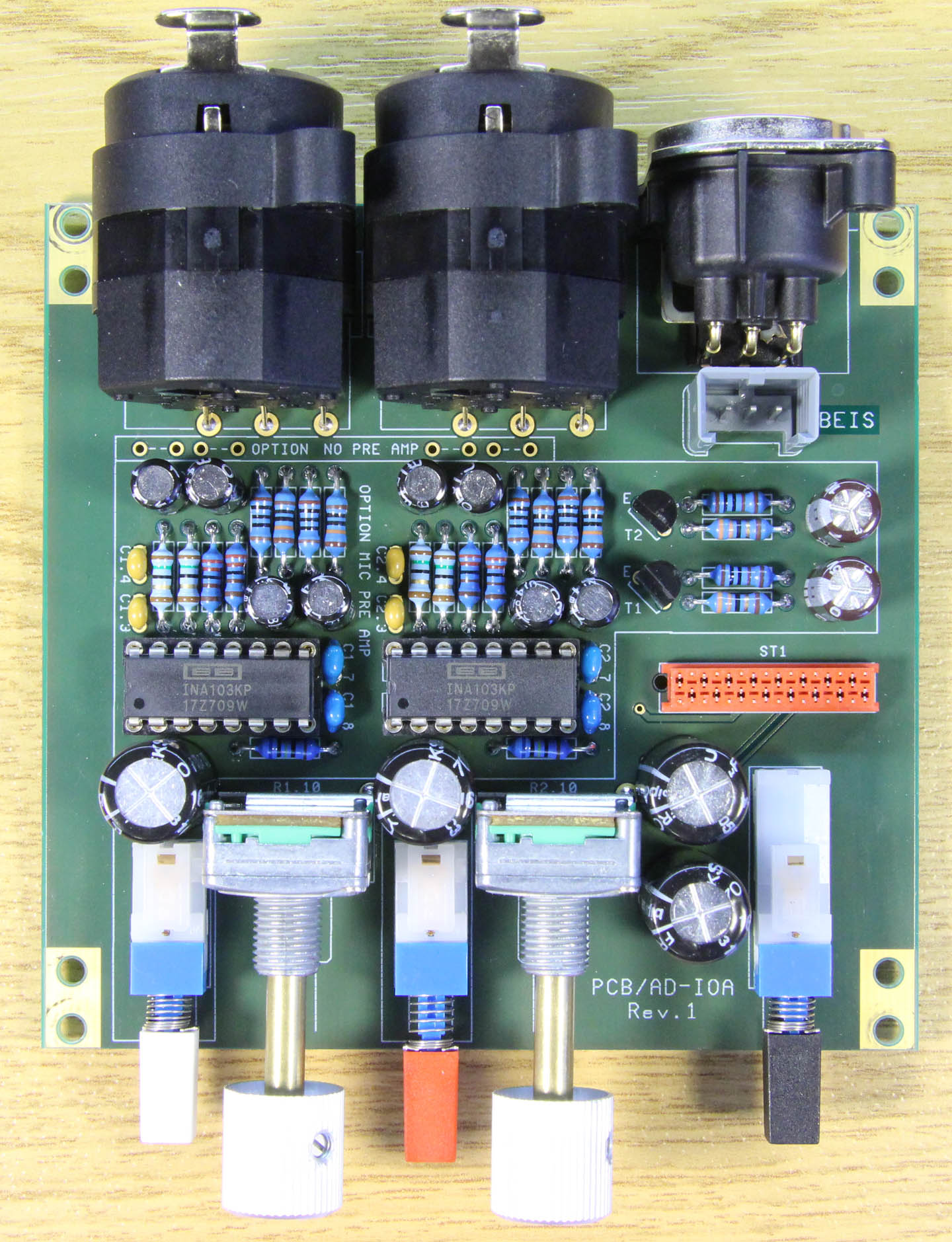
AD-IOA 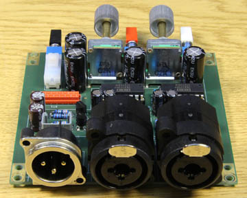
The AD-IOA (Input/Output with active circuitry) is a multi-purpose
module for the AD24QS. It provides:
- A dual channel very low-noise microphone preamplifier with
balanced XLR inputs
- 20 or 40 dB gain can be selected individually for each
microphone input
- Balanced line inputs with TRS jacks
- Automatic selection between TRS and microphone input when
the TRS plug is inserted
- A pushbutton to select between the unbalanced RCA jacks on
the AD24QS and the balanced inputs on the AD-IOA
- 2 potentiometers to control the AD24QS' gain between +6 dB
and +36 dB
- One XLR balanced digital audio output (AES3 or AES/EBU resp.)
- Connection between the AD24QS and the AD-IOA with one 16
pole ribbon cable and for the digital audio output one more 3
wire IDC-cable
- Same form factor as the AD24QS
This is the AD-IOA block diagram:
Click to view the full block
diagram
For the circuit diagram of the AD-IOA, have a look either at
the GIF-file or the PDF-file.
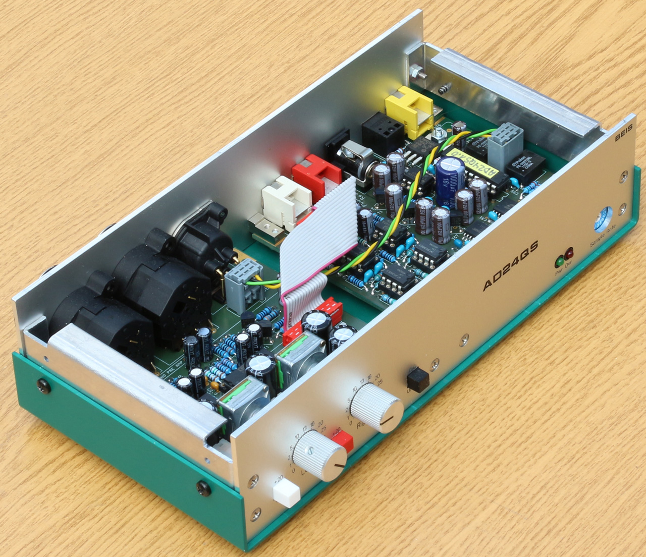
 Wiring
The AD24QS and the AD-IOA are connected with each other by
- one 16 wire IDC ribbon cable, 100 mm long, for audio
signals and power supply
- one 3 wire IDC cable, 135 mm long, for the AES3/EBU
digital audio output.
Both cables are prepared and intended to be used as on this
photo.
Modifications on the AD24QS for
the AD-IOA
All additional components on the AD24QS which are required
for these modifications are part of the AD-IOA kit.
- For the interconnection populate the ribbon cable connector
ST2.
- For the gain control populate R3 and R20. For the recommended
gain range of 30 dB R3 = R20 = 30R is necessary.
- When the variable gain potentiometers are used the minimum
input sensitivity is risen from 2 VRMS by 6 dB
to 1 VRMS. In order to suit to e.g. usual CD
players the minimum input sensitivity needs to be less than 2 VRMS
and hence should be decreased again by replacing R8/11/25/28
(2k2) by 5k36 and R9/10/26/27 (2k4) by 5k9. This measure reduces
the minimum input sensitivity by approx. 7.4 dB. I.e., in
connection with the AD-IOA and its potentiometers for variable
gain the minimum sensitivity becomes 2.35 VRMS.
- For the digital audio output populate the corresponding digital
audio output components R37, R38 (56R each), TR1 and ST4.
The DIY Section
For different reasons I am allowed to sell these converters
as kits and thus for DIYs only.
 Is
it difficult?
Is
it difficult?
I expect sufficient experience from people to assemble the
kits. I don't explain how to read resistor values, how to discriminate
a 100 µH inductor from a 100 Ω resistor,
which components are polarized and so on.
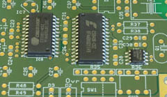
Though I don't find it to be really difficult to solder SO-IC
packages, on the kits the 3 SO-ICs (CS5361/81, CS8406 and
MK2703) are already soldered.
What even happens to me is to mix up similar looking resistors,
put components in the wrong places, rotate ICs by 180° or
forget to solder all joints. Usually all this soon becomes quite
obvious and can easily be corrected.
 Kits
Kits
The kits I provide come with all necessary electronic and mechanical
parts for the basic version of the ADC, the AD24QS-K (unbalanced
inputs, no gain adjustment, no connector for balanced inputs,
no 3rd digital audio output.) The GAL is programmed.
The kits come without an enclosure, front or rear panel - just
as you can see on the photos.
See the BOM AD24QS-K (bill of material)
what is actually included in the AD24QS-K kit.
In case you order the AD-IOA kit, all components that are additionally
required on the AD24QS-K come with the AD-IOA kit.
See the BOM AD-IOA (bill of material)
what is actually included in the AD-IOA kit.
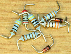
Normally, all axial components, i.e., resistors, diodes and
inductors, come cut and bent. This saves a lot of assembly time
for you and may help that the assembly looks neater. Not all components
on the board need to be populated. They are partially intended
for options. Which one is to be populated and where is shown in
the assembly drawings.
9 jumpers, indicated red in the assembly drawing, must be placed:
4 at ST2, 1 at SW1 and 2 each at L1 and L3. For the longer wires
I prefer colored insulated ones because it looks better.
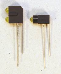
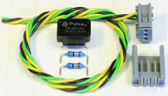
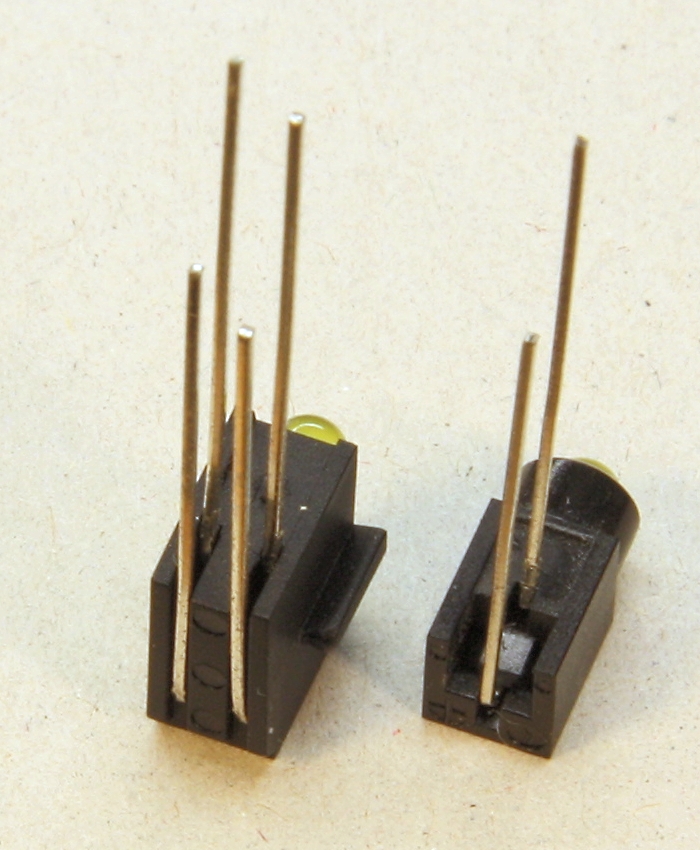
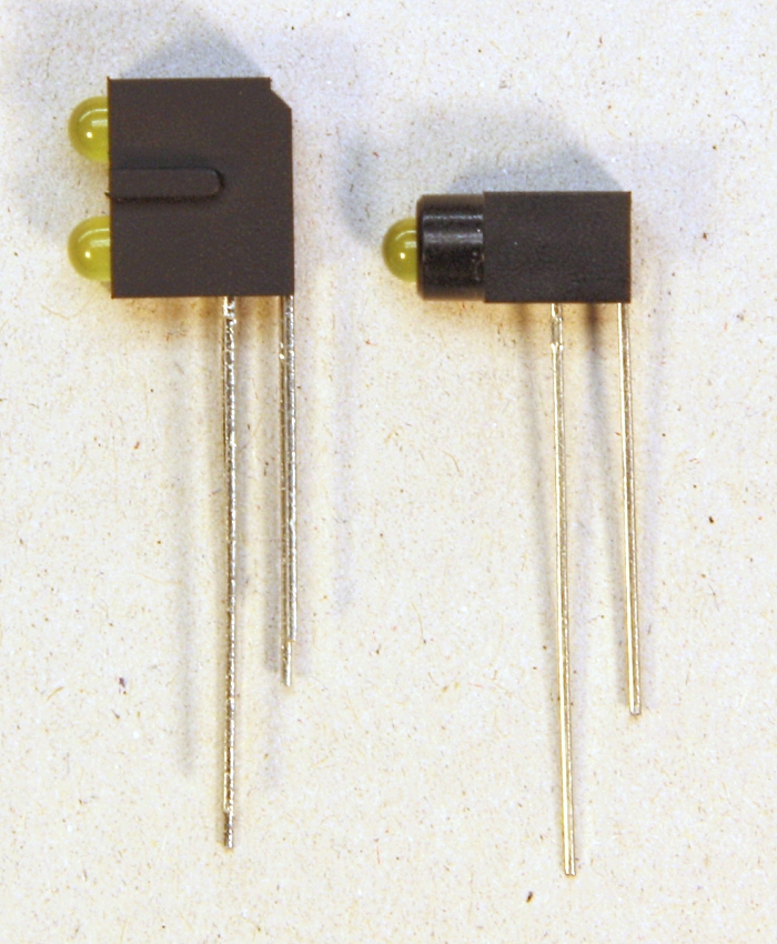
Preparing the LEDs
The photos on the right show how the LEDs must be built into
the LED holders, their polarities (the long leads are anode)
and how the leads must be bent. Click on the photos to enlarge
them.
Note that both LED holders have an up- and an underside. |
|

|
|
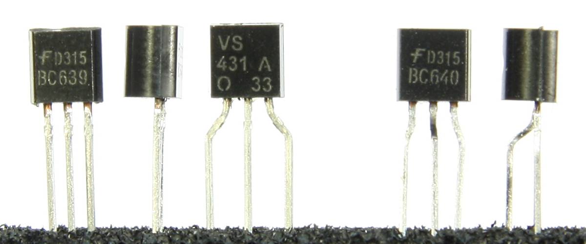
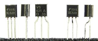 Preparing
the TO92 Cases
Preparing
the TO92 Cases
The photo on the right shows how to prepare the transistors
and ICs in TO92 cases. Unfortunately I cannot easily get the leads
bent as originally planned, so they must be bent correctly by
hand during assembly. I intended the pad layout in a triangular
shape with 0.1" (2,54 mm) pitch. Today most TO92s come with all leads
close to each other in one row (both left transistors) or, the
tape-and-real version, like the TL431 in the middle.
Do not force TO92s with such unsuitable leads into their holes!
Try to bend them like the rightmost ones which I bent manually.
Each lead is bent twice. Do not bend the leads directly at the
case because the case as well as the leads would be very much
stressed and endangered. After bending, they should more or less
"fall" into their three holes in the PCB.
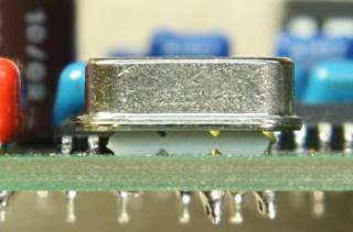
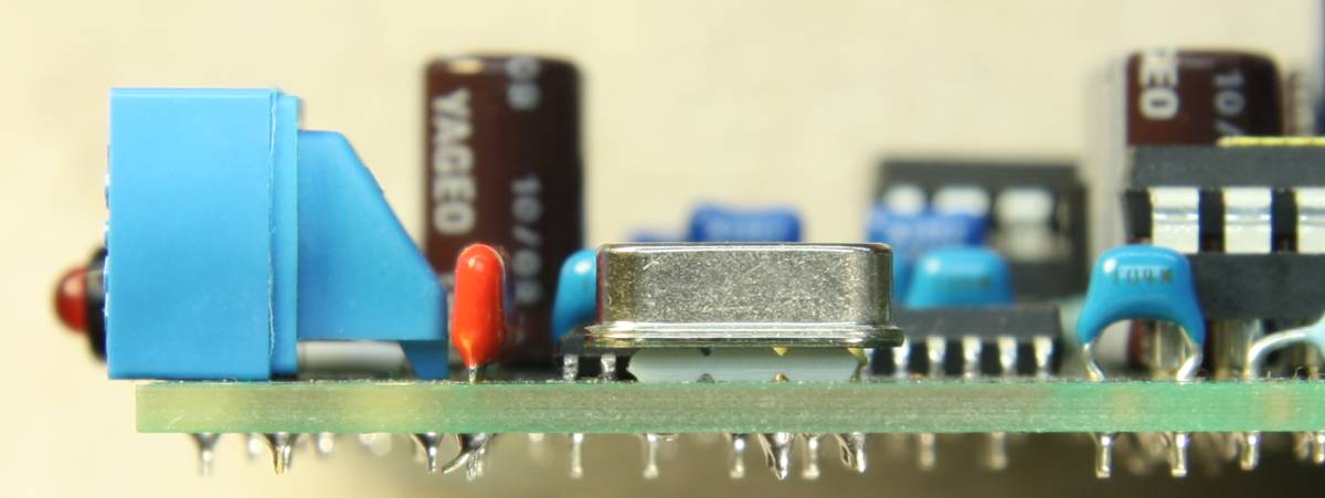
Distance Holder for the Crystal
Place the distance holder underneath the crystal so that the
crystal's case doesn't have direct contact to the PCB and the
leads are soldered at some distance from the case. |
|
|
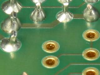
Gold Flash Plated PCBs
Up to now I used HAL PCBs (hot air levelling, which basically
means tinned). They are shown on many of the photos you see here.
The newest PCBs I ordered have more expensive gold flash plated
surfaces. I didn't choose that because it "sounds better"
or because the board might become more reliable - I simply experienced
that because of the different colors forgotton solder joints
are very clearly visible. Also in the past I experienced that
forgotton solder joints are one of the most common causes for
malfunction. With this in mind I actually had no other choice
than to use gold flash plated PCBs. |
|
|
Assembly Drawing
Here you find the assembly drawings:
Optional components or Values in the Assembly Drawings
|
|
R8/11/25/28 |
R9/10/26/27 |
ST2 |
R3/R20 |
R37/38 |
TR1 |
ST4 |
IC1/2/3/4 |
IC8 |
|
Former standard kit |
2k2*
|
2k4*
|
Jumpers |
|
|
|
|
OPA2134 |
CS5361 |
|
Option "Flagship" (now: Standard) |
|
|
|
|
LM4562 |
CS5381 |
|
Necessary modifications for options (can be done even if they are not needed):
|
|
In connection with AD-IOA |
5k36* |
5k9* |
Yes |
30R |
56R |
Yes |
Yes |
|
|
|
Option Balanced Inputs |
Depending on the user's
requirements, see text.
2k2/2k4 or 5k36/5k9
are typical choices.
|
Yes |
|
|
|
|
|
|
|
Option Gain Control |
Yes |
30R
|
|
|
|
|
|
|
Option AES3 Output |
|
|
56R |
Yes |
Yes |
|
|
|
Others |
Refer to text |
*: These are the default values for the kits. The can be changed according to the user's
requirements, see text.
Options
From revision 4 on 120 dB Dynamic Range (formally option "Flagship"
Chip Set) is no longer an option but standard. The CS5381 is a 120 dB ADC, pin compatible to
the 114 dB CS5361. It has slightly more power consumption
and is significantly more expensive than the CS5361. In order
to maintain its extremely high dynamic range I recommend to use
better (and again significantly more expensive) low-noise, dual
op-amps, e.g. LM4562
from National Semiconductors instead of OP2134. With CS5381 and
LM4562 I measured an increase of 6 dB for the dynamic range.
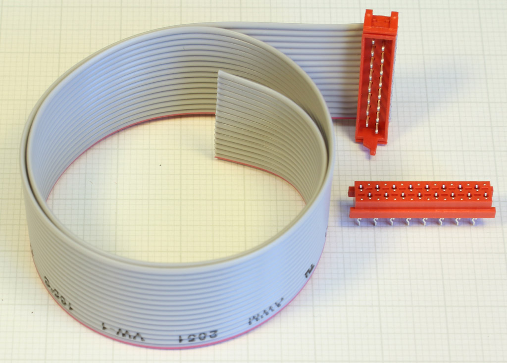
 Input
Selector, Balanced Inputs, Variable Gain (Option Set for balanced
inputs): In case you want one or more of these features but without
the AD-IOA, I can offer the particular Micro-Match connector set
with the appropriate ribbon cable for the on board connector
ST2, as you can see at the right hand photo. You can also refer
for these connections to the circuit
diagram of the AD-IOA.
Input
Selector, Balanced Inputs, Variable Gain (Option Set for balanced
inputs): In case you want one or more of these features but without
the AD-IOA, I can offer the particular Micro-Match connector set
with the appropriate ribbon cable for the on board connector
ST2, as you can see at the right hand photo. You can also refer
for these connections to the circuit
diagram of the AD-IOA.
Input Selector: With an additional switch (2 x change-over
per channel), wired to the Micro-Match connector, it is possible
to switch between the on-board unbalanced RCA inputs and the external,
balanced XLR or TRS inputs. The switch must be connected where
in the schematics currently
the 4 jumpers at ST2 are indicated. Also refer to the circuit
diagram of the AD-IOA.
Balanced Inputs: XLR connectors or TRS jacks
are wired to ST2 as shown in the circuit
diagram of the AD-IOA or as follows:
|
Signal |
|
XLR |
|
TRS |
|
Left In |
|
Right In |
|
Ground |
|
Pin 1 |
|
Sleeve |
|
Pin 4 |
|
Pin 14 |
|
Pos. |
|
Pin 2 |
|
Tip |
|
Pin 5 |
|
Pin 15 |
|
Neg. |
|
Pin 3 |
|
Ring |
|
Pin 3 |
|
Pin 13 |
Variable Gain: By using additional resistors
variable gain is available. Populating R3 and R20 and one external
variable resistor each between ST2 pins 1/2 and ST2 pins 11/12
the gain can be increased according to the table shown in the
circuit diagram. E.g., with R3 = R20 = 430 Ω a maximum
gain of 15 dB is achieved. The external variable resistors
may be either switched for a set of precise fixed gains or potentiometers,
preferably negative logarithmic ones. You may also refer to the
circuit diagram of the AD-IOA.
 Balanced
AES3 Output (Option Set for AES3 output): For the balanced
digital audio output another digital audio transformer, a connector
set and two resistors are needed. The option "Set for AES3
output" contains them all as you can see on the right hand
photo. This feature is also supported by the AD-IOA and these
components are also part of the AD-IOA kit.
Balanced
AES3 Output (Option Set for AES3 output): For the balanced
digital audio output another digital audio transformer, a connector
set and two resistors are needed. The option "Set for AES3
output" contains them all as you can see on the right hand
photo. This feature is also supported by the AD-IOA and these
components are also part of the AD-IOA kit.
Different Gains: By replacing the resistors R8, R9,
R10, R11 and R25, R26, R27, R28 the conversion gain can be increased
or decreased. The rules are:
RA = R8 = R11 = R25 = R28 and
RB = R9 = R10 = R26 = R27, where
1.1 x RB = 1.2 x RA resp. RB = 1.2 / 1.1 x RA
This ratio is exactly met with
1.1 kΩ and 1.2 kΩ
2.2 kΩ and 2.4 kΩ
3.3 kΩ and 3.6 kΩ
Very close value pairs with noticeably less than 1% error are
3.9 kΩ and 4.3 kΩ
4.7 kΩ and 5.1 kΩ
5.1 kΩ and 5.6 kΩ
6.2 kΩ and 6.8 kΩ
7.5 kΩ and 8.2 kΩ
9.1 kΩ and 10 kΩ
With values from the E96 series, of course, many more combinations are possible.
Deviations from this ratio cause a reduction of the common mode rejection in the preamplifier/filter, which would not necessarily be critical.
R A for a specific full-scale input voltage UFS
is: RA = UFS x 1.1kΩ / 1V
The full-scale input voltage UFS is: UFS
= RA x 1V / 1.1kΩ
Note: The input sensitivity cannot be decreased arbitrarily
because the input buffers may overdrive. This occurs with unbalanced
input signals 6 dB earlier than with balanced input signals.
With 12 V power supply the limits are:
- For unbalanced inputs (where only one input buffer carries
the full input signal) it must not be decreased below +14.7 dBu
(= 4.2 VRMS), i.e.,
R8 = R11 = R25 = R28 <= 4.7 kΩ and
R9 = R10 = R26 = R27 <= 5.1 kΩ.
- With balanced input signals it can be decreased another 6 dB
down to +20.6 dBu (= 8.3 VRMS), i.e.,
R8 = R11 = R25 = R28 <= 9.1 kΩ and
R9 = R10 = R26 = R27 <= 10.0 kΩ.
- When variable gain potentiometers are used the situation
becomes more complex. This is why in connection with the AD-IOA
even for the unbalanced inputs resistor values of 5.36 kΩ
and 5.9 kΩ are allowed.
Experimental switch: In the layout I provided a quad
DIL-switch for
- the User-Bit U
- the Validity bit V
- the emphasis bit (which indicates that the audio signal is emphasized) and
- turning off the digital high-pass filter inside the CS5361
(which enables the CS5361 to convert DC voltages)
EMC chokes: For an improved EMC (electro-magnetic compatibility)
the board is prepared for two common mode chokes, L1 and L3. One
is for the power supply input, the other one for the unbalanced,
digital audio output. I pay attention to EMC performances but
I am not able to test them. I prepared the chokes "just in
case". Under normal circumstances they are not required.
Anyway, the ADC should always be installed into a well
shielding enclosure!
Word Clock Synchronization: I used to offer a word clock
synchronization module, the XS-AD24. Should you be interested,
read about it in the article "XS-AD24:
VCXO-based Word Clock Synchronization for the Audio-ADC AD24QS".
I'm sorry that the XS-AD24 is currently not available because
it is either awfully difficult or awfully expensive to purchase
appropriate VCXOs (case 5 x 7 mm, 5 V, pull range >
+/- 100 ppm). Maybe in future it will become available again.
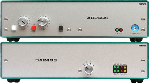
Enclosures and Front Panels

 For
my units I used an SG 206
or SG 210
resp. enclosure from the (German) company Fischer
Elektronik. In contrast to the pictures you see here, these
enclosures are no longer available in opal green from the manufacturer.
I still stock SG 206 in opal green (SG 206 GO),
but the SG 210 now comes in black (SG 210 S).
For
my units I used an SG 206
or SG 210
resp. enclosure from the (German) company Fischer
Elektronik. In contrast to the pictures you see here, these
enclosures are no longer available in opal green from the manufacturer.
I still stock SG 206 in opal green (SG 206 GO),
but the SG 210 now comes in black (SG 210 S).
Front panel, enclosure and board are directly fixed to each
other using the element
5.60.422 from the (German) company Ettinger,
available at Bürklin.
You need not necessarily to use the enclosure I used. The boards
can easily be built into other enclosures. For these enclosures
I provided detailed dimensional drawings:
Note: The dimensional properties of revisions 3 and 4 are identical.
You will see there how the board is fixed within the SG206/SG210
and how it can alternatively be fixed directly to other front
panels. Of course you may also use four stand-offs, distance bolts
or distance tubes to fix the board on the bottom of your enclosure.
The drilling positions can be found in the dimensional drawing,
too.
Details for Front and Rear Panel Mounting
The mounting elements 5.60.422 are intended to be used
either standing (particularly in the SG 206 enclosure, left
photo) or lying, e.g. in the SG 210 enclosure (right photo)
or behind any other front panel.
Front and Rear Panel Design Files
The front and the rear panels shown above are manufactured
by Schaeffer AG (in Europe)
and are available in the US from Front
Panel Express, LLC, too. You need the design files for these
panels, then you just have to send them to the manufacturer and
you'll get a perfectly milled and engraved panels, as the photos
show. You may also modify the design files with the front panel
design software "Front Panel Designer" German,
English
or French
(it's free and very convenient) so that it fits to other enclosure
of your choice.
All companies mentioned above have international branches,
e.g. in the USA.
How to order...
... is explained on page AD/DA24QS_Order.
| Last update: January 23rd, 2022 |
Questions? Suggestions? Email Me! |
Uwe Beis |


