| |
|
Exact and Incorrect Phase Comparators
![]() German Version: Exakte und fehlerhafte Phasenkomparatoren)
German Version: Exakte und fehlerhafte Phasenkomparatoren)
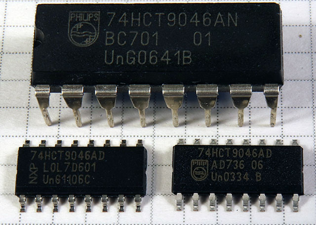
Why, of all things, is the 74HCT9046 no longer in production?
| |
|
Exact and Incorrect Phase Comparators
![]() German Version: Exakte und fehlerhafte Phasenkomparatoren)
German Version: Exakte und fehlerhafte Phasenkomparatoren)
Why, of all things, is the 74HCT9046 no longer in production?
In electronics, phase comparators are very often used as part of a PLL (Phase Locked Loop), often for very high frequencies. Also, if two or more audio signals are to be digitized with the same clock, they must be synchronously clocked. Within one device this usually results by itself, but with many different devices, e.g. in a recording studio, a central clock must supply all devices with a master clock. This master clock is called word clock and has the frequency of the sampling rate of typically 44.1 or 48 kHz, although in practice 32 to 192 kHz are encountered from time to time.
In connection with the development of audio ADCs, which are to be externally synchronizable by a word clock signal, a phase comparator for the relatively low frequency word clock signal is also needed. Every reasonably experienced developer will spontaneously say: "Yes, a 74HCT4046 fits perfectly, it not only has a suitable phase comparator, it also has a VCO to generate the internal master clock of mostly 128 or 256 x word clock frequency".
So - no. Apart from the fact that I didn't want to use an R/C-based VCO with its comparatively high jitter, but a VCXO (Voltage-Controlled Crystal-Oscillator), I was skeptical whether the phase comparator PC2, which is the only one in question, doesn't have a "quirk" that I can't accept. This was triggered by the remark "No dead zone of PC2" in the data sheet of the 74HCT9046 from Philips/NXP/Nexperia.
The PC2 output is provided to obtain not only frequency equality, but also the phase equality of a signal with a reference signal, which is required in this case. The details can be found in the data sheets. The PC2 output provides high or low pulses with the duration of the phase difference in case of phase differences. This is how it is supposed to be, but:
At small phase differences in a range of (measured) about 10 ns, the PC2 output of the 74HCT4046 remains in high impedance state.
This is easily explained by the circuit principle of the PC2. In a PLL the phase of the output signal would drift constantly in a range of approx. 10 ns around the phase of the reference signal, and only at the borders of the dead zone the phase comparator "notices" that there is something to be adjusted. Then, however, not with correspondingly small differential pulses, but immediately with pulse widths corresponding to the actual phase difference. In professional audio technology, such behavior is sacrilege, and certainly not only there.
This means: A phase jitter of about +/-5 ns is a built-in property of the 74HCT4046.
By the way, this is in principle also true for many other PLL ICs, which use the same comparator principle, only perhaps to a lesser degree.
So Philips (when they were still called that) came up with something better. The IC is called 74HCT9046 and has not only a correctly working phase comparator, but also an improved VCO, although the latter is not needed in my situation.
And of all things, this IC has been discontinued by NXP (or Nexperia?)!
I don't know of any comparable phase comparator. There may be some, but it wouldn't help much for a finished design. Also, the 74HCT7046 only has a normal PC2. So I "bunkered down" a supply of 74HCT9046s still available NOS from the Far East and tested them. (They are really original 74HCT9046).
A clock pulse is conducted by two phase delays into two clock pulses, whose delay times can be controlled in opposite directions, and given to the reference and signal inputs of a 74HCT4046 and a 74HCT9046.
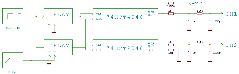
The modulation signal is a low-frequency triangle signal with 1 - 10 Hz and is generated by a function generator.
The PC2 output signals of the two phase comparators are filtered by low-pass filters and displayed. The PC2 output of the 74HCT4046 must still be pulled slightly to VCC/2 with a high impedance resistor to obtain a display where 1. there is a mean voltage in the dead zone which 2. also depends on the length of the differential pulse. The 74HCT9046 still needs a resistor RSET to determine the current of the PC2 output.
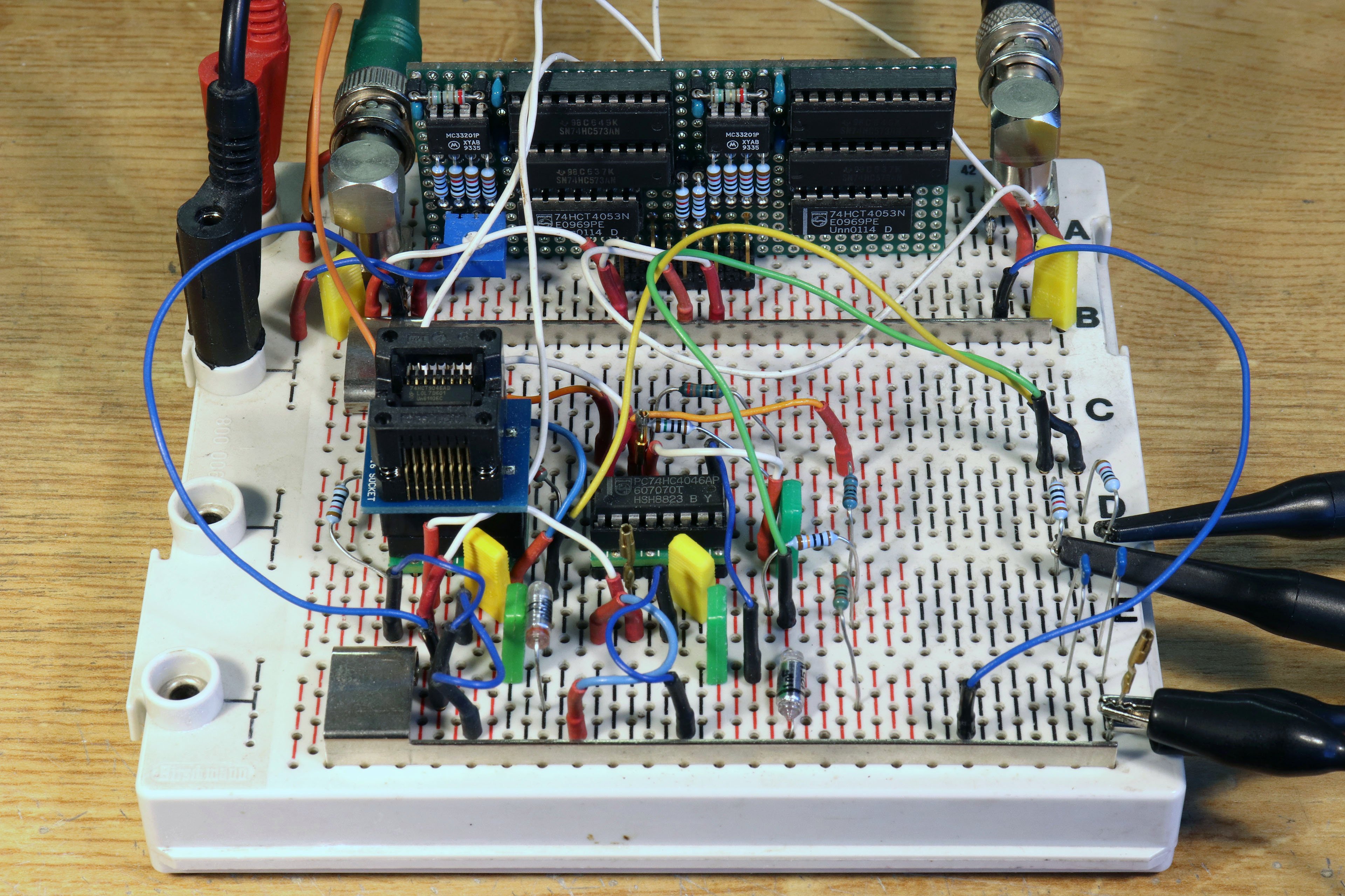
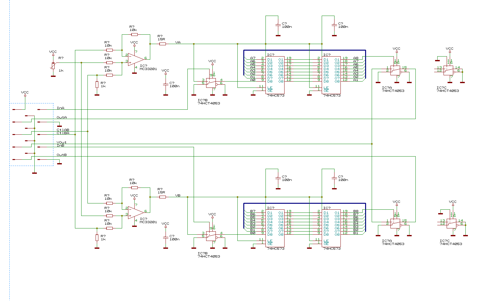
The circuit of the signal delay unit can be found here. In principle, two chains, each with 16 buffers connected in series, delay the signal depending on their operating voltage. Level converters at the inputs and outputs provide for the perfect adjustment to the operating voltage of 5 V. Two differential amplifiers modulate the operating voltages of the buffers.
Built up on a plug-in board, it looks like this:
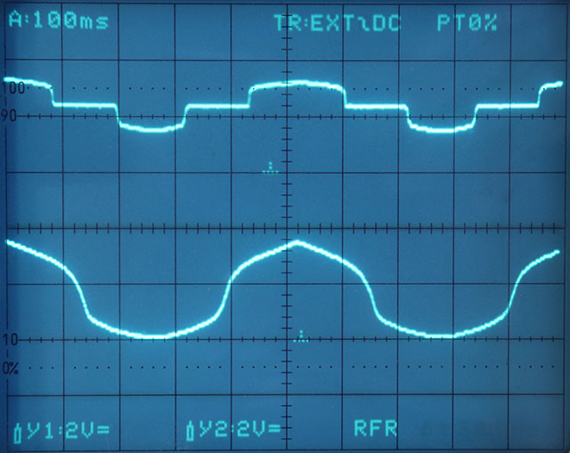
At low phase deviation, here about +/-12 ns, the dead zone of the 74HCT4046 is clearly visible. But also that the 74HCT9046 shows a higher, but not jump-like steepness of the output signal in this range.
The following picture shows the output signals at about +/-120 ns phase deviation.
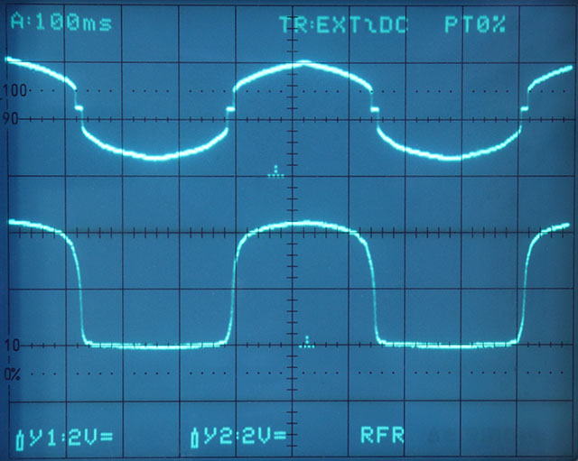
The erratic onset of the differential pulses at the edges of the dead zone can also be seen well here.
Should I need in the future more than the 74HCT9046, which I stockpile, but which are no longer available at all or only at horrendous prices, I would be pleased about tips, which suitable alternatives there are. So ICs, which can be used as pure phase comparators, which do not have a dead zone. And with which not only, as with a simple XOR or e.g. a so-called flywheel synchronization, frequency, but also phase equality can be achieved.
| Last update: October 11th, 2021 | Questions? Suggestions? Mail Me! | Uwe Beis |