| |
|
(Another) P48 to T12 Adapter
-with XLR input and output -
![]() (German Version: (Noch ein) P48-zu-T12-Adapter)
(German Version: (Noch ein) P48-zu-T12-Adapter)
| |
|
(Another) P48 to T12 Adapter
-with XLR input and output -
![]() (German Version: (Noch ein) P48-zu-T12-Adapter)
(German Version: (Noch ein) P48-zu-T12-Adapter)
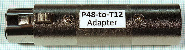
I have a very nice HF condenser microphone with XLR connector, but unfortunately it requires 12 V phantom power (T12). Adapters and circuit diagrams for adapters that allow such older T12 microphones to operate on 48 V phantom power (P48) microphone inputs are many. Here is another one where the circuit differs only in one detail from the usual circuit, but I am concerned here with a construction of the adapter in a handy and readily available XLR housing.
The circuit differs from the frequently found variant only in that there are two double diodes. With these diodes possible overvoltages at the T12 microphone should be made harmless. These overvoltages might occur when plugging the P48 side and could endanger a T12 microphone connected at the same time.
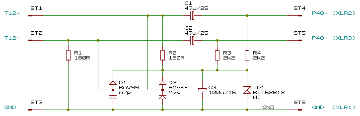
The dimensioning of the resistors is also as usual: With two 2.2 kΩ resistors connected in series to the two standardized 6.8 kΩ resistors of the P48 source and a 12 V zener diode, the result is a zener current of (48-12 V)/((6.8+2.2 kΩ)/2) = 36 V/4.5 kΩ = 8 mA, which is also the maximum supply current of the microphone.
The capacitors are chosen to provide as much capacitance as possible, but at the same time all three of them fit side by side in the intended package, which has an inner diameter of just under 16 mm. In addition, they must not be too high.
There are inexpensive small XLR adapter housings that suggest themselves to build such an adapter in there. But it's not that easy: The space for such an additional circuit is not exactly lush. Connecting pins have to be bent in a complicated way and the solder connections of the XLR socket and the plug have to be shortened.
In the end, the adapter looks like this:
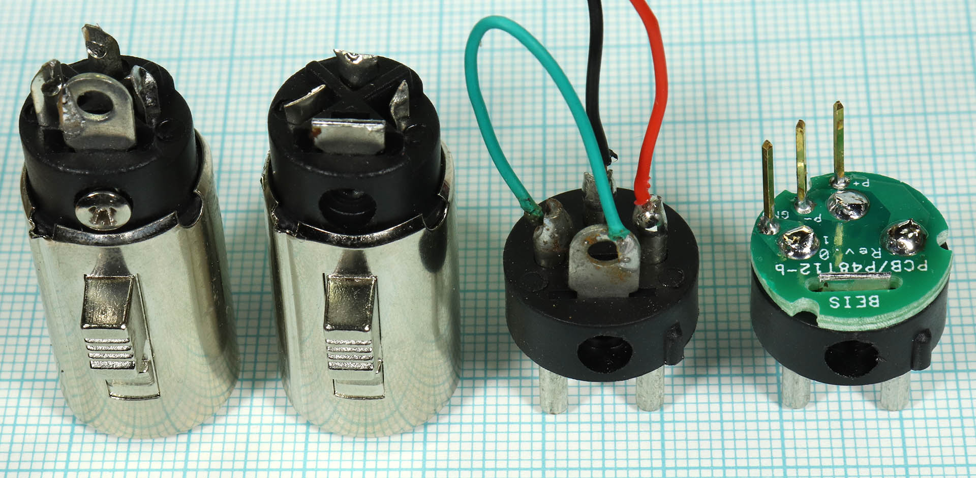
Inside, the housing has 2 x 3 ribs, 3 are on the socket side, 3 more are at other locations on the plug side:
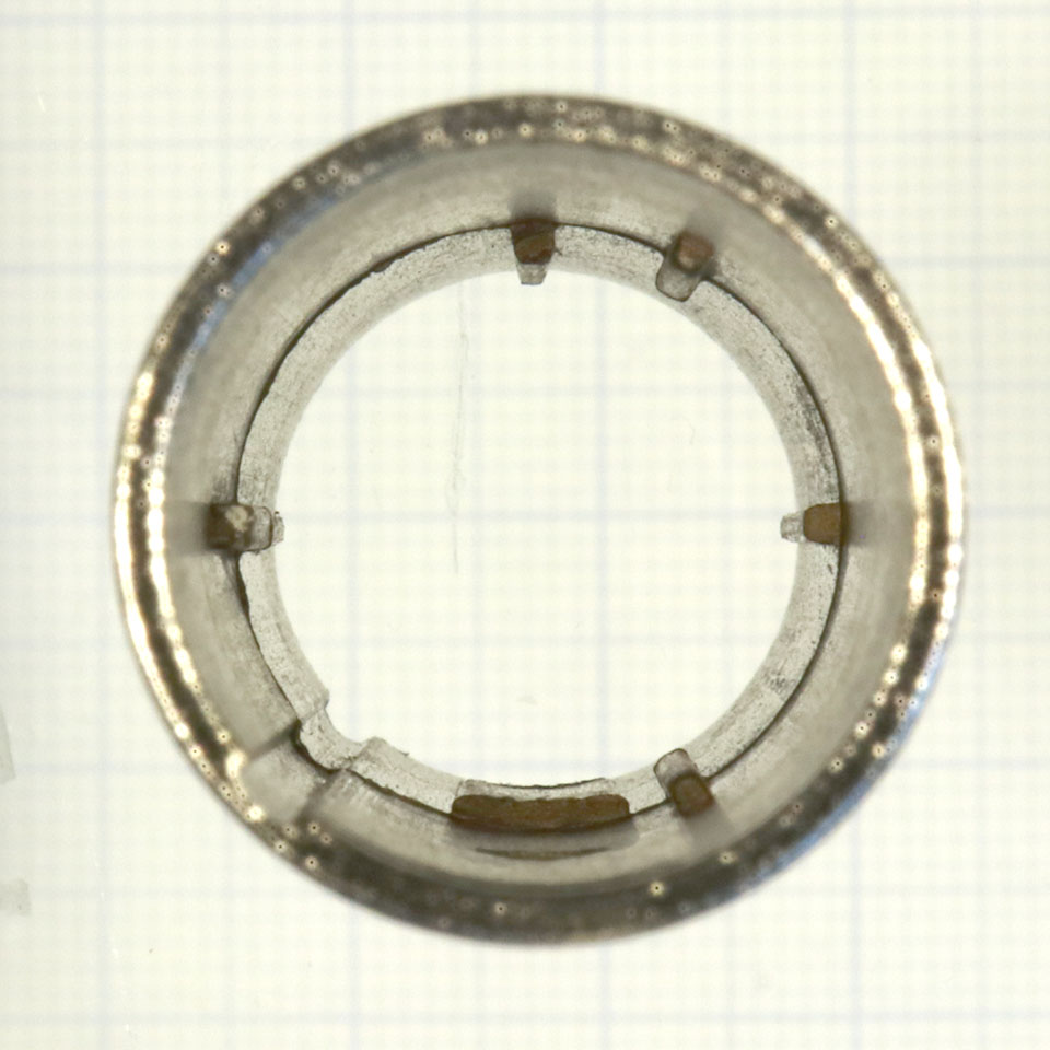
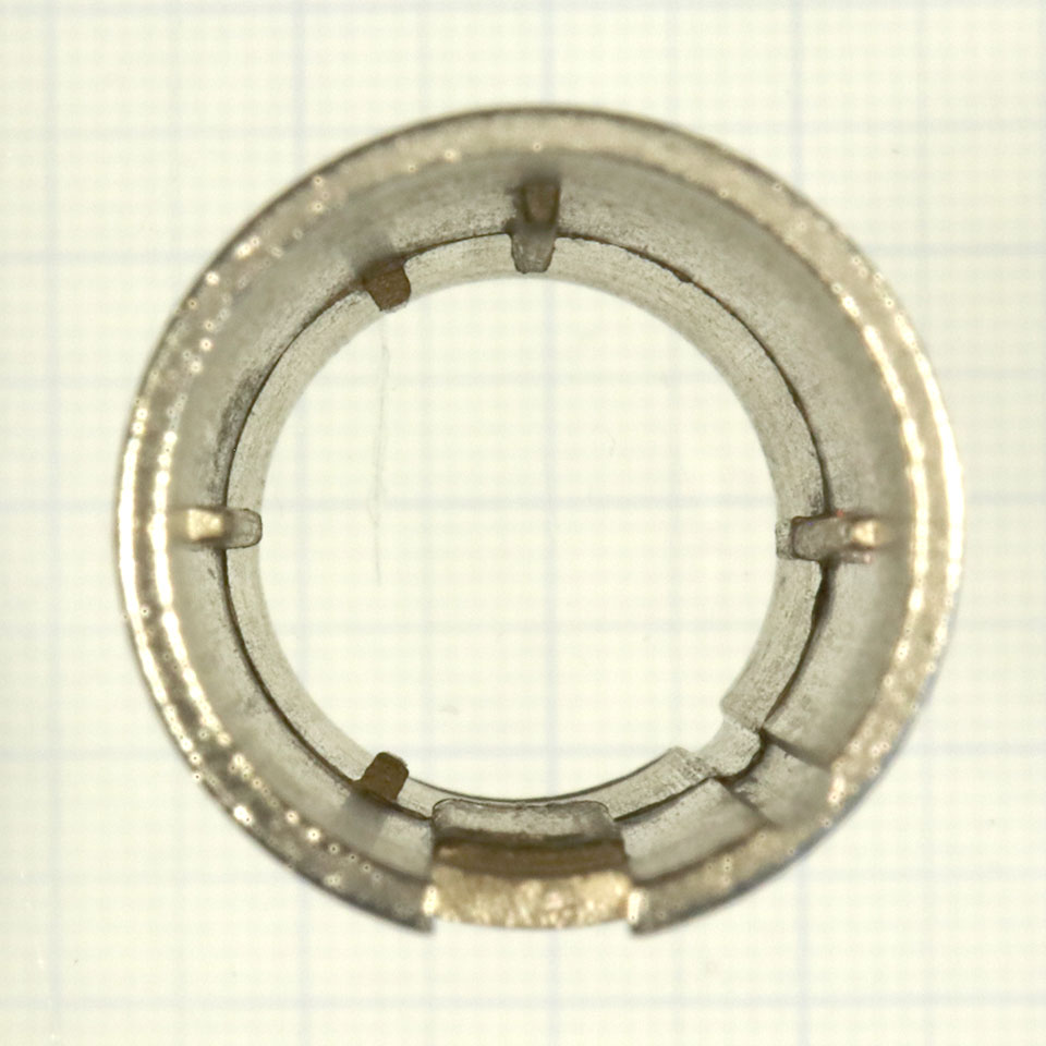
Connector side Socket side
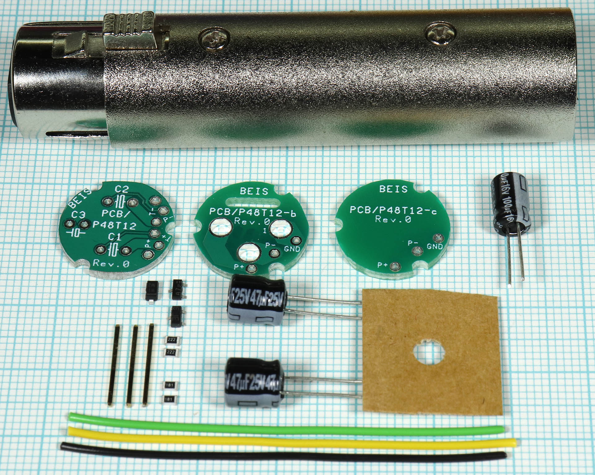
In contrast to an earlier design, there are now 3 PCBs:
The PCBs are designed to have cutouts where the ribs are on the connector side. This ensures that the electrolytic capacitors do not come into conflict with the ribs.
The PCB/P48T12 still needs to be populated with the SMDs and the electrolytic capacitors. The legs of the electrolytic capacitors should be shortened so that they protrude less than the height of the SMDs from the PCB.
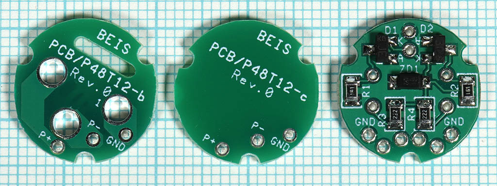
The 3 PCBs. The PCB/P48T12 does not yet contain the electrolytic capacitors.
The soldering legs of the XLR connector and the XLR socket as well as their ground lugs have to be shortened considerably. Those of the XLR connector so far that they just protrude through the PCB/P48T12-b:
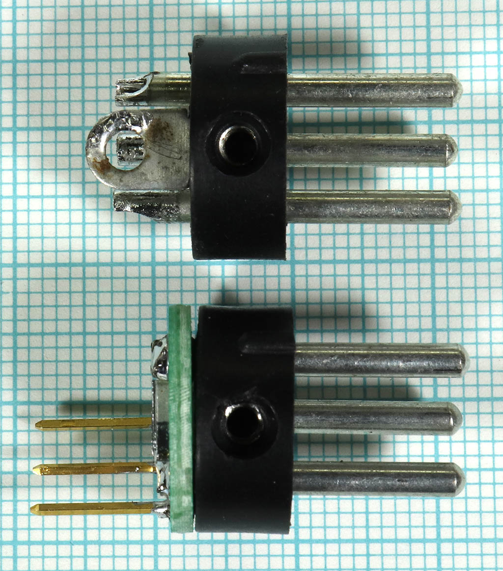
The PCB/P48T12-b should lie flat on the pin carrier.
3 pins from a normal pin header (0.635 x 0.635 mm²) must be soldered exactly perpendicularly into the 3 soldering pads of the PCB/P48T12-b. If they are just a little bit tilted, the later assembly will be difficult or even impossible. For this purpose the solder lugs on the PCB/P48T12-b are drilled so narrow that the pins have to be pressed in with some force and thus are already very perpendicular by themselves. Nevertheless it is recommended to check this and if necessary to adjust it a little bit.. They should be soldered in such a way that they do not protrude at all or at most only very little through the PCB.
Unshortened (with the original strands) and shortened XLR connectors.
Together with the other two PCBs a stack is formed, but not soldered yet. This is a good way to test if the stack can be inserted into the case. A little "hooky" is normal, but please do not use force. If necessary, the three pins can be easily bent.
Relative positioning in the housing. There is little space for the strands.
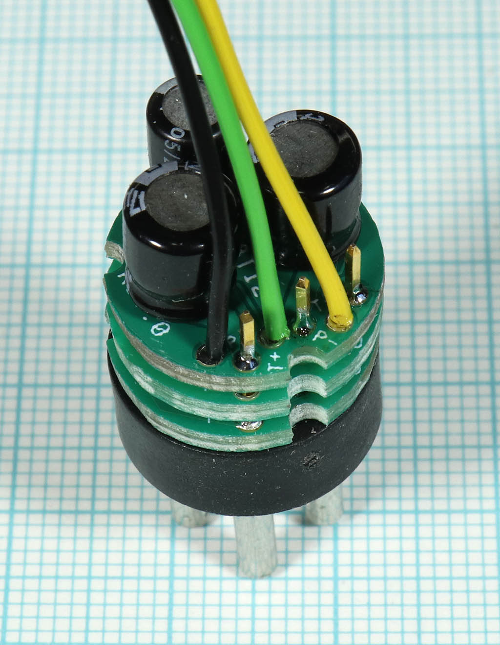
If everything fits, the wires can be soldered into the PCB/P48T12. They should also protrude only a little on the solder side. Then assemble the stack and solder the PCB/P48T12-b to the pins (the PCB/P48T12-c does not need to be soldered):
The plug side is installed in the housing and the stranded wires are soldered to the socket side. It is essential to pay attention to the correct polarity! No connection is made between pin 1 and the housing as in the original adapter. Grounding and shielding are to be defined elsewhere, but remain separated here.

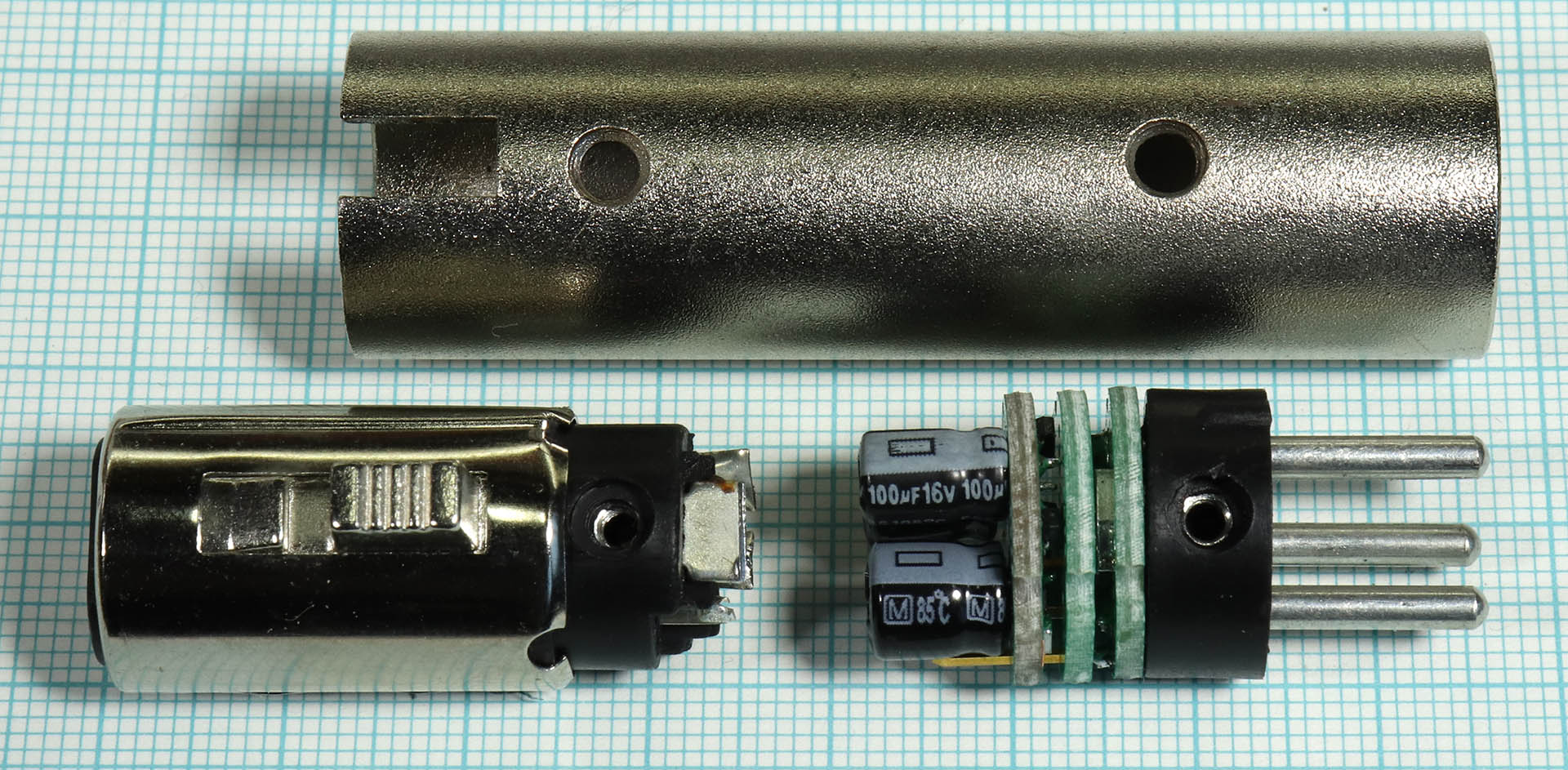
There is only a little space in the housing for the stranded wires. To prevent them from being forcefully stuffed into the housing, I recommend turning the socket a few times before installation. This way the strands will rather voluntarily lay into the housing in the form of a spiral.
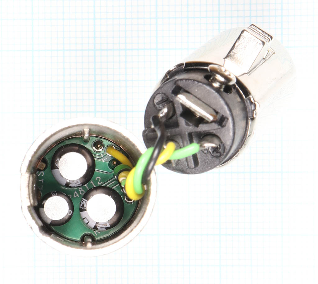
View into the housing
| Count | Componet | Source |
|---|---|---|
| 1 | Printed circuit board, PCB/P48T12 | Beis.de |
| 2 | Resistor, 180 Ω, size 0805 | Various |
| 2 | Resistor, 2.2 kΩ, size 0805 | Various |
| 2 | E-Cap, 47 µF, 25 V, D <= 7 mm, H <= 8 mm, RM 2,5 | E.g. Mouser ECE-A1EKA470I |
| 1 | E-Cap, 100 µF, 16 V, D <= 5 mm, H <= 8 mm, RM 2 | E.g. Mouser 80‑ESS107M016AC2KA |
| 1 | Z-Diode, 12 V, Bauform SOD123, z.B. BZT52B12‑E3‑08 | E.g. Mouser 78‑BZT52B12‑E3‑08 |
| 2 | Dual diodes, series connection, size SOT23, z.B. BAV99 | E.g. Mouser 771‑BAV99235 |
| 1 | XLR/XLR male/female adapter housing | E.g. Ebay |
| 3 | Stranded wires 55 - 60 mm, pins from pin headers |
In contrast to the photo the PCB/P48T12 and the PCB/P48T12-b
have been revised again and both now have the Rev.1.
If you are interested in rebuilding this adapter: I still have a few sets of components left over from development, but unfortunately no matching housings. The housings that can be obtained now have the ribs in a different place, and the PCBs do not fit. A solution could be to mill or grind the ribs on the connector side, but I haven't tried that yet. If nevertheless still interest exists if necessary please inquire. However, I have not yet thought about a price.
| Last update: May, 23rd, 2023 | Questions? Suggestions? Mail Me! | Uwe Beis |