| |
|
Repair Power Supply Spectrum Analyzer Advantest R3361A
- and certainly the whole series R3261, R3361, R4131 -
(![]() German Version: Reparatur Netzteil Spektrumanalysator Advantest R3361A)
German Version: Reparatur Netzteil Spektrumanalysator Advantest R3361A)
Update 2023-02-25
| |
|
Repair Power Supply Spectrum Analyzer Advantest R3361A
- and certainly the whole series R3261, R3361, R4131 -
(![]() German Version: Reparatur Netzteil Spektrumanalysator Advantest R3361A)
German Version: Reparatur Netzteil Spektrumanalysator Advantest R3361A)
Update 2023-02-25
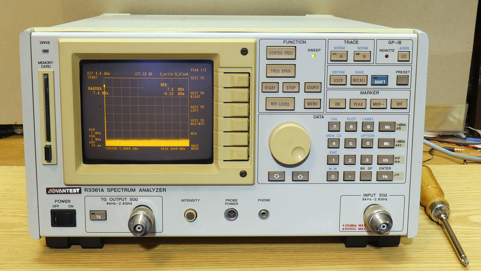
I inherited a very nice Advantest R3361A spectrum analyzer a long time ago at the dissolution of my employer's hardware development department. Originally it cost about as much as "an upper middle class passenger car". I had worked with it for many years. In the later years - it's been a lot of years - I always noticed a sweetish smell after turning it on. But it did its job.
Until a few months ago. In the middle of a measurement, it went off. Oh dear. This is not a HiFi amplifier, where you can often repair something without service documents. Nevertheless I dared it - and won. Actually even twice.
The hope that the problem was the power supply was fulfilled, as well as the hope that I could get to the power supply and that it was not seriously defective. But it was an adventure.
The sweet smell came from leaking electrolyte from several(!) electrolytic capacitors. That seems to have evaporated or otherwise disappeared shortly after switching on. Interesting: When desoldering such an electrolytic capacitor, there is the same smell. Disassembly is not trivial, but if you know how to do it, it's not witchcraft. I had changed most, i.e., all of the larger electrolytic capacitors during the first repair, some of which had "wet feet" from the electrolyte. The spectrum analyzer then worked again for a few months - then the sweetish smell came back. And not much later it had "ticked" again when switched on, but worked otherwise.
Thus the second repair. I didn't find an electrolytic capacitor with "wet feet", and I could measure the correct capacitances and ESRs of all remaining electrolytic capacitors, i.e. the smaller ones that hadn't been changed yet. This did not look good. On one, the bottom seemed to be a bit crooked, so I unsoldered it for a closer look. And lo and behold - the smell was back when I un soldered it, even though it was completely dry underneath. A strong indication!
So I changed the rest of the electrolytic capacitors as well. Now the spectrum analyzer is working again, and it doesn't smell (again). Hopefully it will stay like this.
This time I had intended to write a repair guide. It seems to be a common fault. We had two R3361A in the company. The other one was also defective at some point - and went for scrap (without my knowledge). Ouch!!!
As far as I could find out, it is a power supply type PTA 465-00 1991-05 from Fujitsu Electromechanical. The output voltages are:
+5.2 V |
1.5 - 5.0 A |
+12 V |
0.5 - 1.5 A |
+15 V |
0.2 - 2.5 A |
-15 V |
0.2 - 1.3 A |
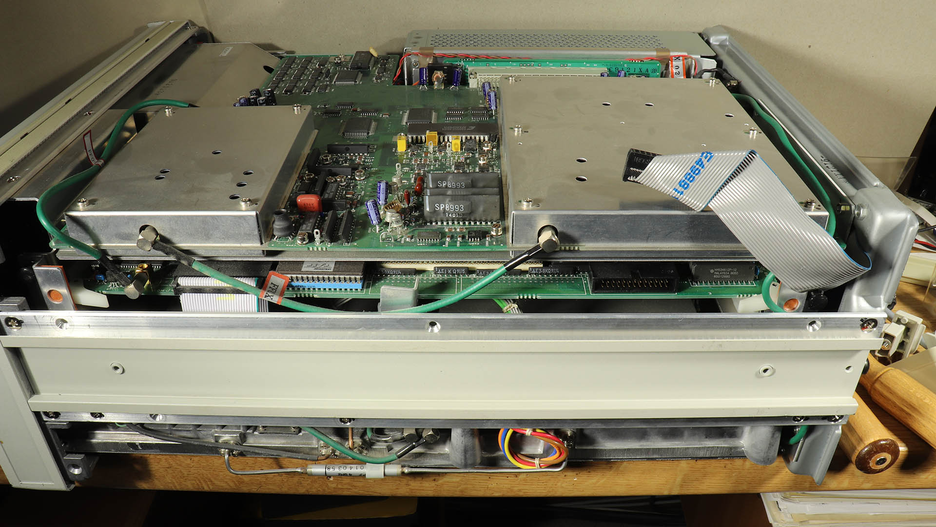
Before you start to change the electrolytic capacitors on suspicion, these operating voltages should be checked. To do this, the power supply must be exposed ready for operation, as I have described below. On the photos below you can see two pin headers on the left, a 2-pin one further in front (or on the photo below), next to it (on the photo above) a 12-pin one.These pin headers are assigned as follows:
O Line snychronization*
O -15 V
O Ground
O Ground
O +15 V
O +15 V
O +5 V
O +5 V
O Ground
O Ground
O Ground
O +12 V
O +12 V (red) To fan
O Ground (black)
*Obviously a logic signal synchronized with the mains power supply that is used for the trigger in "line mode."
(All photos can be clicked for an enlarged view).
Update: After the first successful repair, the sweetish smell reappeared a while later. Again I had to open the spectrum analyzer. But I had made the experience that it is easier than I originally described. It is not necessary to remove the plastic panels on the sides and the rear panel. The corresponding sections are therefore grayed out and indented:
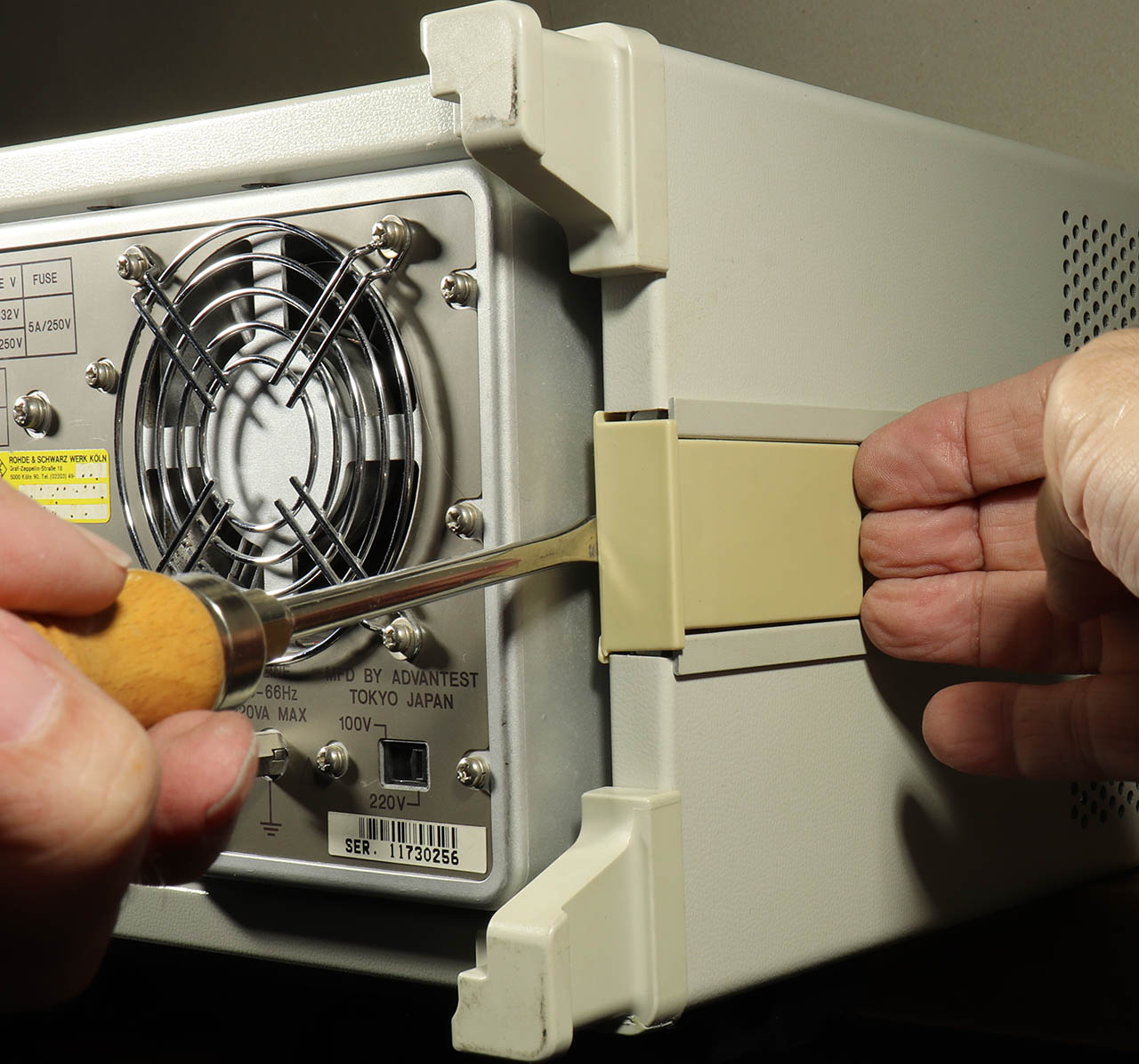
Not necessary: First, push the plastic side panels of the profiles out backwards. It helps if you push them out a little, as in the photo. But only a little! Better push with more force!
The 4 feet at the back are unscrewed, then the top and bottom cover can be removed.
Not necessary:It is now recommended to disconnect the ribbon cable connector for the GPIB interface (and maybe other, optional interfaces?):
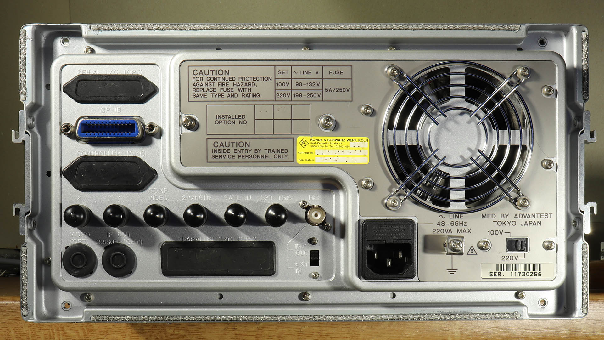
Not necessary:Then the rear panel can be unscrewed. Two larger countersunk screws in each of the side profiles and another 8 small screws in the circumferential recess of the rear panel, but with one exception:
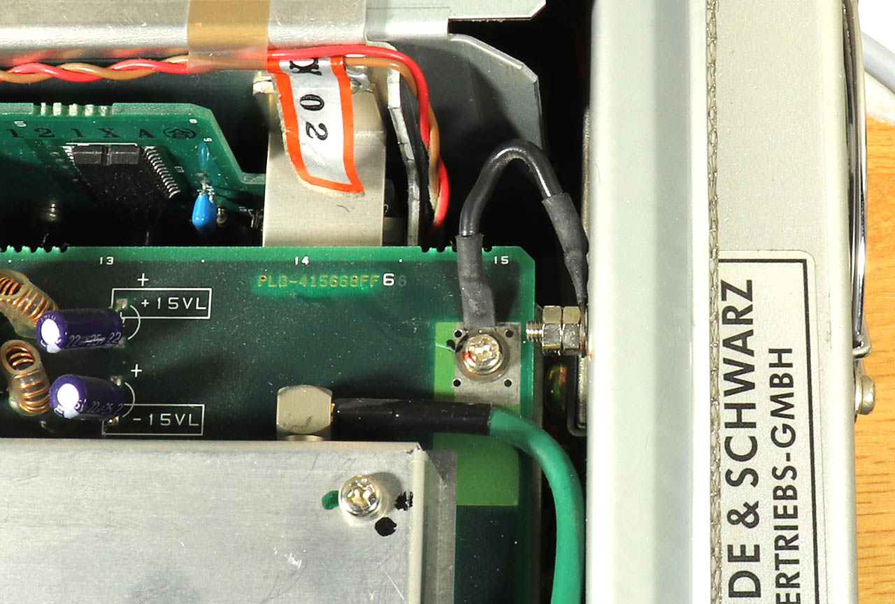
Not necessary:The exception is one of the 8 screws with two nuts and a ground wire, which is better to unscrew on the PCB:
Not relevant here:The remaining cables to the rear panel are laid in such a way that you do not have to disconnect them.
The left side profile is completely unscrewed. Two more large and some small countersunk screws:
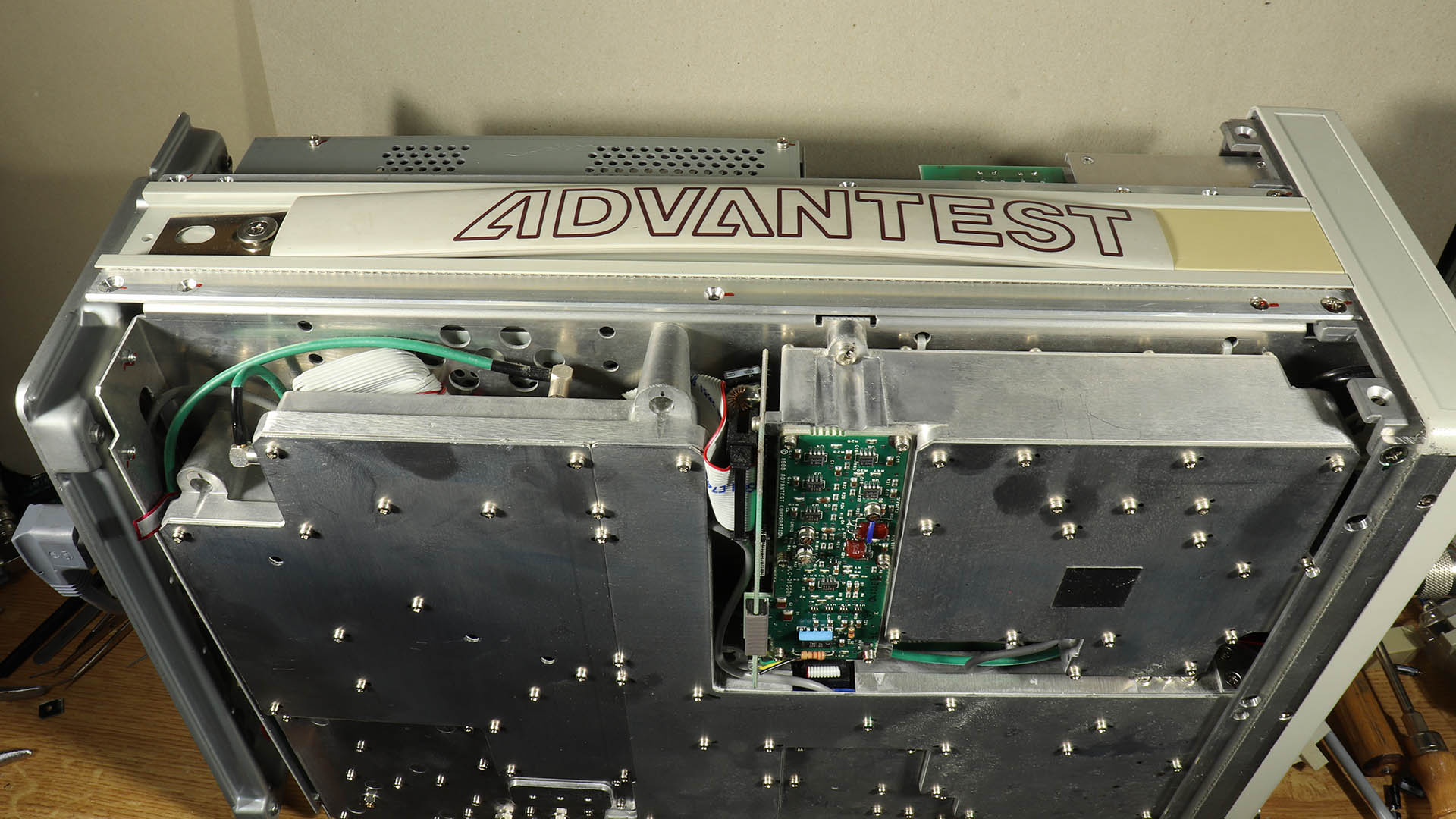
The power supply is in the now accessible cage. The 4 screws visible here on the cage cover are removed:

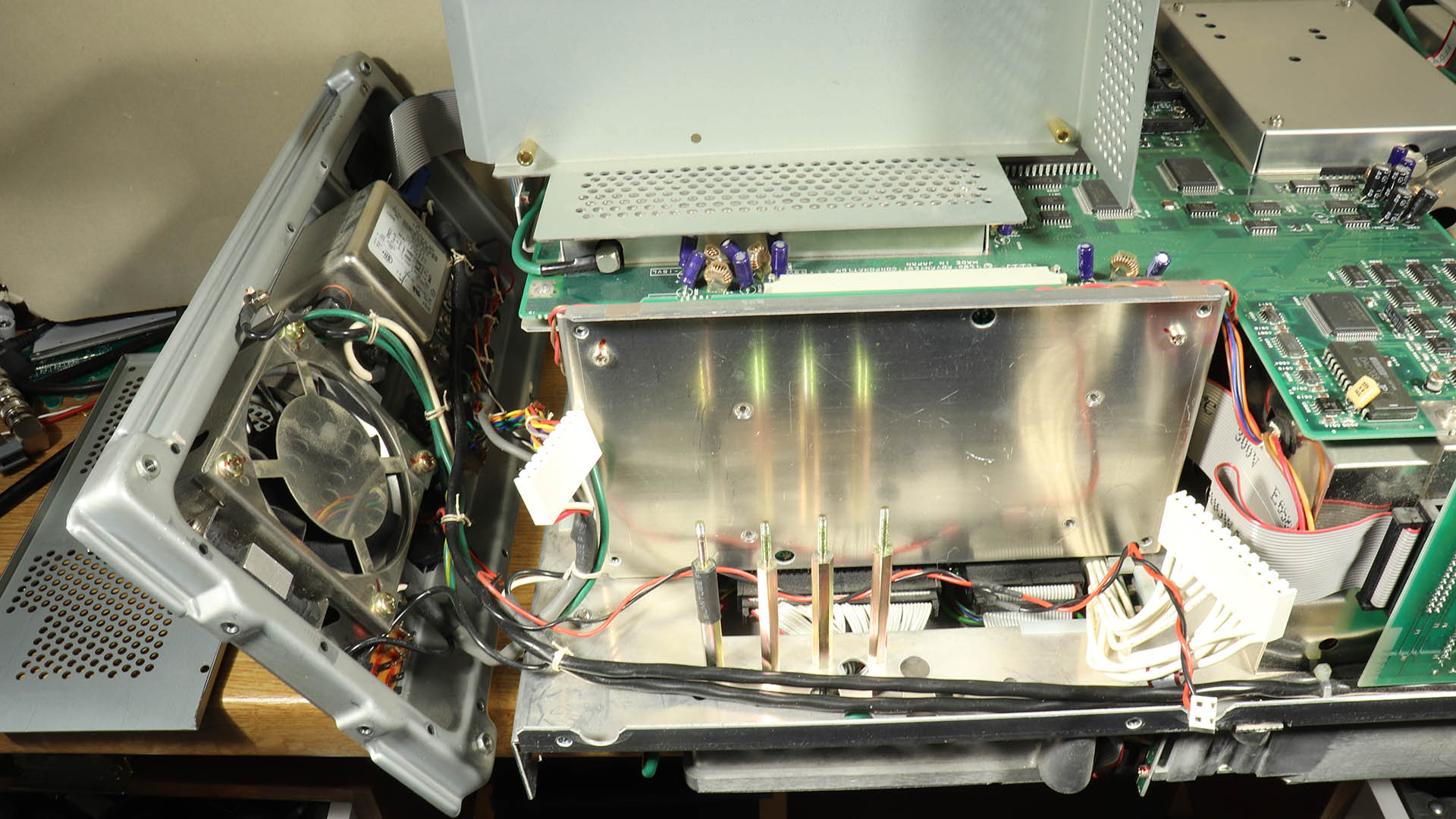
Then 4 long threaded bolts are removed inside where the 4 screws were (for the photo I put them inside the unit), and the power supply can be unplugged and removed together with the cage bottom. With 2 more screws the power supply is separated from the cage bottom.
Update: If the rear panel has not been removed, the power supply can also be removed after removing its cover. It then looks like this:
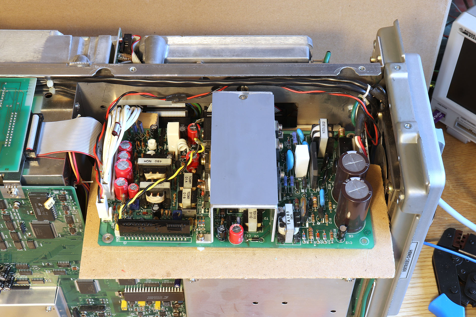
The power supply is here on an insulation board, because during the second repair I wanted to determine in operation where the smell was coming from. But it didn't smell at all anymore - somehow the problem had resolved itself. Strange. I hope it stays that way. However, some of the electrolyte had obviously gotten into the pins of the connector on the low voltage side. One of the contacts was out of order - so something needed to be done after all.
End with the update, now continue in the original text:
So now we can start. On the photo you can see (despite a lot of dust) all electrolytic capacitors, and all are already replaced:
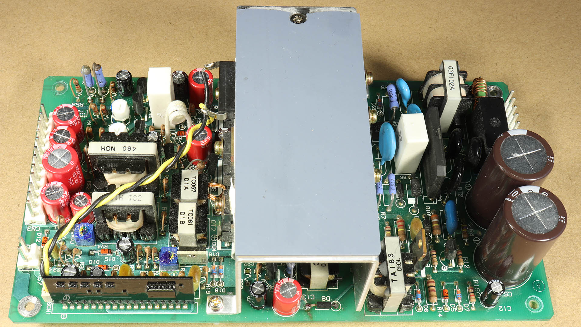
There should be 19 electrolytic capacitors:
Quantity |
Value |
Diameter [mm] |
Grid [mm] |
2 |
470µ/200V |
23 |
10 |
1 |
3300µ/10V |
14 |
5 |
1 |
680µ/25V |
10 |
5 |
2 |
470µ/25V |
10 |
5 |
1 |
470µ/10V |
7.5 |
3.8 |
2 |
330µ/50V |
10 |
5 |
1 |
220µ/50V |
10 |
5 |
2 |
47µ/63V |
9 |
3.8 |
1 |
10µ/100V |
5 |
3.8 |
1 |
4µ7/100V |
5 |
2.5 |
5 |
1µ/100V |
5 |
2.5 |
I hope that I have not made a mistake.
Assembly: Reverse. Pay attention to the cable routing, do not forget anything, but otherwise no special tricks are required.
I hope I can save some of these units from being scrapped. If anyone succeeds in repairing them, I would be very happy to hear of your success. Also, if other spectrum analyzers are the same in this regard would be interesting. But also in case of failures: I would also be happy to share such experiences here.
Finally, here is a link to a post in a French forum that also discusses experiences and further information on repairing an R3361A: https://vae-tech.forumactif.org/t316-remise-en-etat-d-un-analyseur-de-spectre-r3361a-advantest
| Last update: January 4th, 2026 | Questions? Suggestions? Mail Me! | Uwe Beis |