| |
|
Current-Induced Resistor Noise
![]() German Version: Strominduziertes Widerstandsrauschen)
German Version: Strominduziertes Widerstandsrauschen)
A collection of experience from experimental measurements
- No scientific treatise -
| |
|
Current-Induced Resistor Noise
![]() German Version: Strominduziertes Widerstandsrauschen)
German Version: Strominduziertes Widerstandsrauschen)
A collection of experience from experimental measurements
- No scientific treatise -
The fact that resistances produce temperature-dependent noise voltages or currents solely by their existence, I presuppose as known. I have described it in the article Resistor Noise. Less known is that an additional noise voltage can occur when current flows through the resistor. This noise voltage depends on the technology of the resistor and of course on the current through or voltage across the resistor and its resistance value. Unfortunately this characteristic is not mentioned or even specified in the data sheets of the manufacturers. At least I have never seen it, with one exception - but I have to admit, I have not seen many data sheets either. The exception was a manufacturer of thin film SMD resistors (Susumu). Because it is also not a natural constant or something similar, this noise cannot be calculated, one can estimate it at best and reduce it partially or completely below its natural noise by suitable circuit technology and resistance selection.
In order not to use the bulky term "current-induced resistance noise" again and again, I take the liberty here of using the actually wrong term "current noise". Strictly speaking, it should actually even be "current-induced resistance voltage noise" or "voltage-induced resistance current noise"...
Measured or explored should be the dependence of the current noise from:
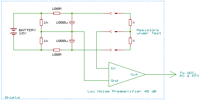
To measure the current noise of the resistors, two identical resistors were connected in series and operated with a symmetrical power supply. Thus the input of the following preamplifier remains nearly DC-free. With the two identical test resistors in series you save a low-noise current source, but of course you have to consider that now not one, but two resistors, which are connected AC-wise in parallel and operated with half the operating voltage each, generate the measured noise.
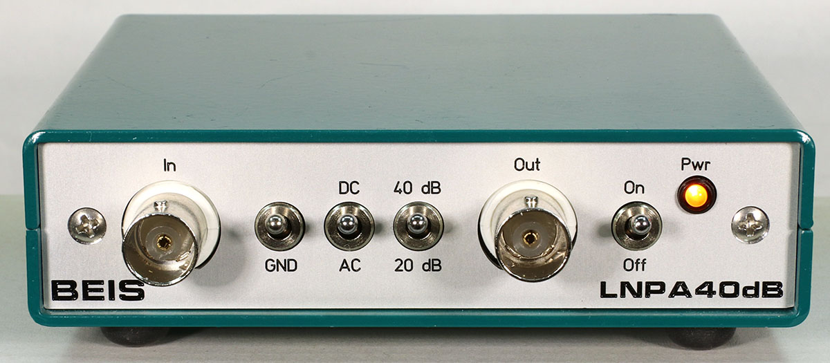 I used my LNPA40dB as a preamplifier, which I developed not least for this test series. It is a low noise, battery powered FET preamplifier with 20 or 40 dB gain. By connecting 4 low-noise FET operational amplifiers in parallel, each with approx. 4.5 nV/sqrt(Hz), the measured input voltage noise of the LNPA40dB is approx. 2.2 nV/sqrt(Hz), which corresponds approximately to the thermal noise of a 290 Ω resistor. FET inputs have virtually no noise current, so the only input noise current comes from a 1 MΩ input resistor required for the bias point. This input noise current is significantly smaller than the input noise current of any operational amplifier with bipolar inputs. However, the operational amplifiers used (OPA1612) already show a significant increase in the typical 1/f noise below 1 kHz, which is clearly visible in the measured noise spectra, but ultimately has no effect on the measured values, since the noise of the resistors also increases in the low-frequency range.
This preamplifier is battery-operated and the power supply of the resistors was also provided by a battery. Measurements of such low voltages with very high spectral resolution reveal the smallest interference signals. A connection to a power supply unit would lead to enormous interference signals in the spectrum even with the best galvanic isolation in the power supply unit. In addition, the entire measurement setup must be completely electrically shielded and operated away from magnetic interference fields.
The output of the preamplifier goes into a 192 kHz/24 bit ADC with a sensitivity of +16 dBu (= 4.89 Vrms) for 100% FS and via USB to the PC, where the spectrum was calculated with ARTA. Each spectrum was calculated with 65536 samples, giving a resolution of approximately 2.9 Hz. In order to obtain smooth and precise curves, approx. 5000 to 10000 spectra were averaged per measurement, resulting in a measurement time of approx. 30 minutes per measurement. In addition there was a multiple of the time I needed to get the whole setup so clean and faultless that the measurements became as flawless as they look now.
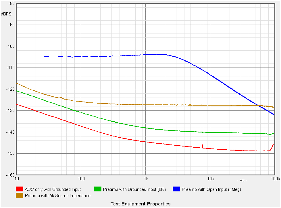
The measurement of the test setup shows the following, diagrams from bottom to top:
The initial properties for the comparisons were as follows: 10 kΩ, SMD thick film, size 0805.
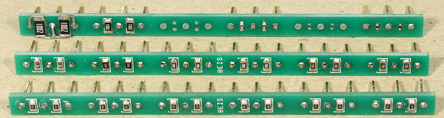 Up to 6 different SMD resistor pairs could be accommodated on small, pluggable PCB strips, from front to back:
- 6 different resistance values (330 Ω, 1 kΩ, 3.3 kΩ, 10 kΩ, 33 kΩ and 100 kΩ),
- 4 different sizes (2010, 1206, 0603 and 0402, 0805 are available on the 1st strip)
- 6 different manufacturers (a 7th manufacturer on the 1st strip)
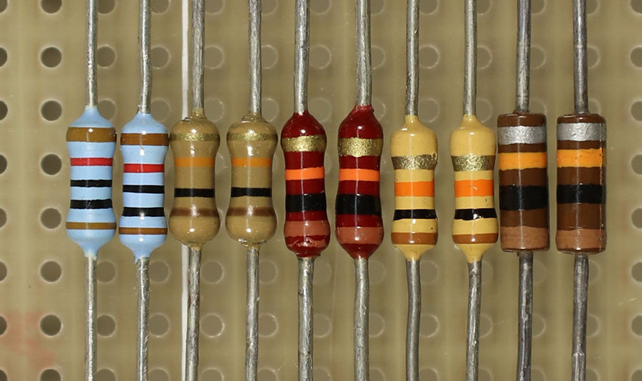 Additionally some THT resistors (leaded resistors) were measured, from left to right: metal film resistor, then 3 different carbon film resistors and on the right a carbon compound resistor.
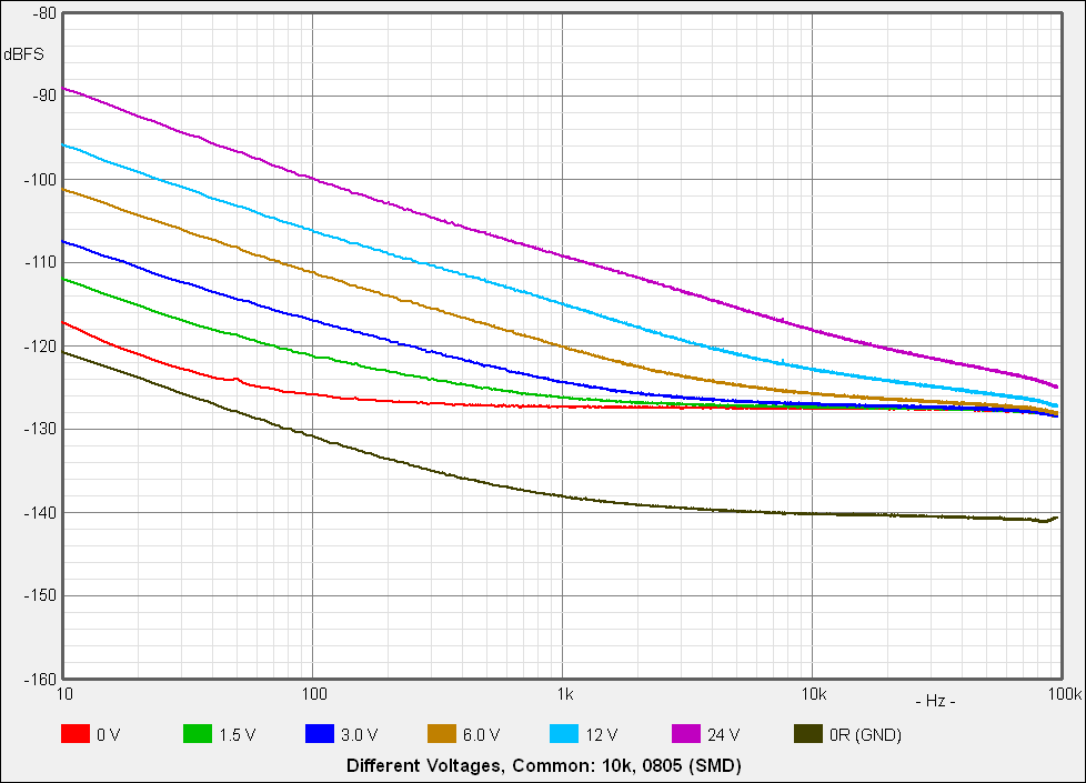
First of all it is noticeable that the noise is proportional to the operating voltage or current.
Also, it is a 1/f noise, so it falls at 10 dB per decade or the noise power is inversely proportional to the frequency. It is also called pink noise. The black line at the bottom is the inherent noise of the preamplifier.
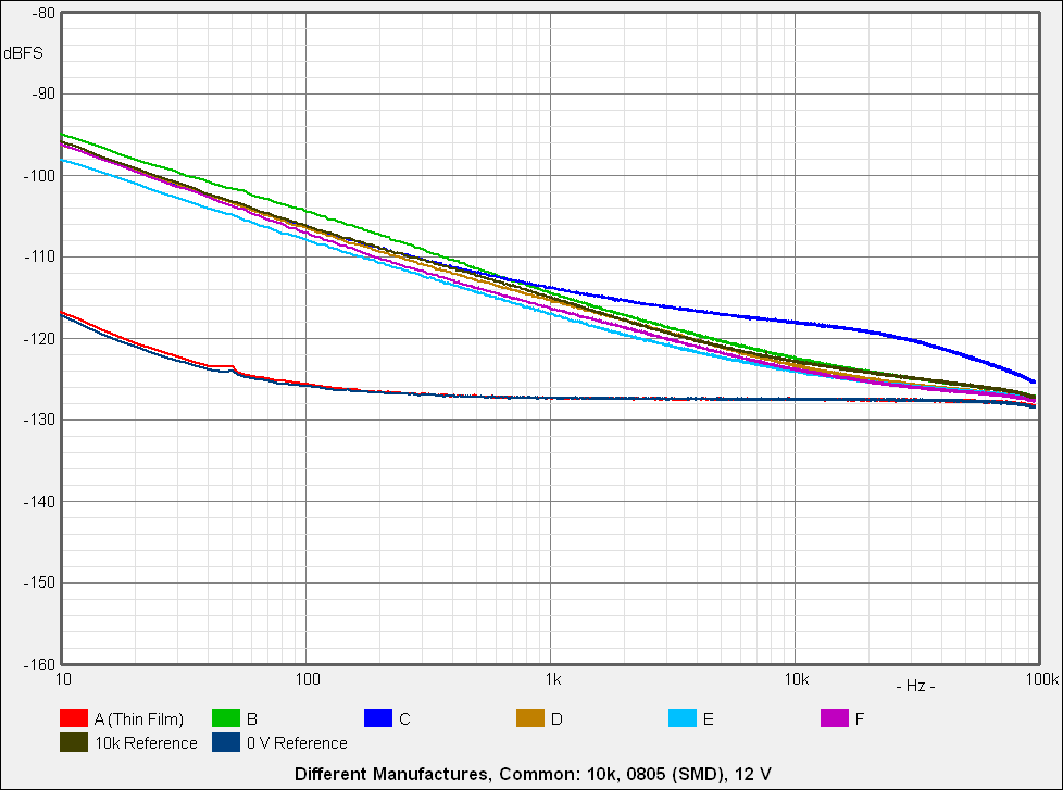
Because the following measurements measure different resistances that were not produced under comparable conditions, e.g. different resistor pastes and different manufacturers, experience is to be gained here as to how big the role of these differences is.
5 different random 10 kΩ 0805 thick film resistors as well as a thin film resistor (manufacturer Susumu, type RR1220P-103-D), all at 12 V, were measured. Thin film resistors are known for low current noise, here you can see that under the given measurement conditions there is actually almost - but only almost - no detectable current noise, but only the normal thermal noise, which is also generated by a voltage-free resistor (0 V Reference).
Otherwise there are no enormous, but not insignificant differences between the different thick film resistances. There is also an oddity with resistor C, which I cannot explain, but can only take note of.

There is no clear dependence on the resistor value. This is obviously due to the fact that despite the same style and technology (thick film) not only the resistor value determines the current noise. Other factors that are manufacturer- or value-dependent also play a major role.
Nevertheless, it can be seen that the lower impedance resistors tend to cause a lower current noise at the same voltage, even though the current is higher.
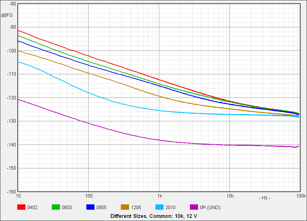
Here, too, the resistors of different manufacturers are used, nevertheless, a clear, but in practice rather not decisive dependence on the size can be recognized: the larger, the lower the noise.
In principle, this can also be derived from the first measurement: If you take 4 resistors and connect 2 each in parallel or in series, you get the same total value on 4 times the area with the same resistance layer. If each of the 4 resistors would produce as much noise as the single resistor, the total noise would remain the same (as would be the case with thermal noise). However, since each of the 4 resistors now only runs at half the voltage, its current noise - and thus also the total current noise - is only half as high.
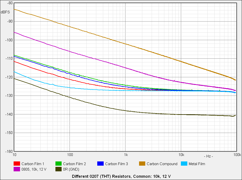
The 3 carbon film resistors, style 0207, generate a moderate current noise, significantly less than the 0805 reference SMD resistor, but also significantly more than the metal film resistor, which generates practically as little current noise at 12 V as at 0 V, see the diagrams above.
If you need a resistor type with really strong current-induced noise, you should use carbon compound resistors...  . In order to save the honor of the carbon compound resistors, it should be mentioned that they are very impulse-resistant, because the actual resistance element is not only a thin layer, but a large-volume mass. And seriously: For the generation of pink noise, which is often used in audio technology and normally only formed with complex filters from white noise, the carbon compound resistor seems to me to be a perfect alternative.
Because I was reluctant to use high-capacity ceramic capacitors in the signal path of audio circuits as a precaution, and because the measurement setup was present, I wanted to make sure that this caution was justified. So I connected a 100 nF, 0805, X7R capacitor with one contact to 12 V voltage, and with another to the high impedance input of the preamplifier. The circuit was a bit more complex than described here, because even the 12 V from a LiIon battery had to be filtered with an R/C circuit, because very strange effects occurred without this filter.
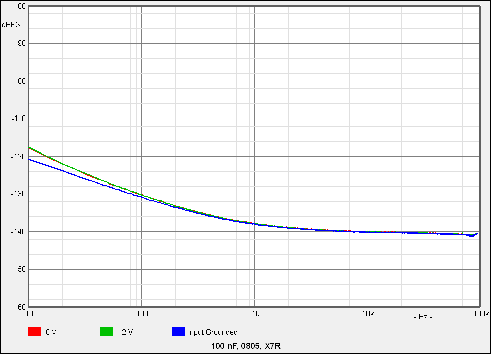
No matter whether with or without 12 V, the noise is identical. In any case, I have not been able to measure or detect any difference. In both cases it is slightly higher at low frequencies than the noise with shorted input because the 1 MΩ input resistor is connected only across 100 nF and not directly to ground, so the noise is caused by the 1 MΩ resistor.
However, this does not mean that ceramic capacitors with a high dielectric constant (i.e. a high εr, e.g. X7R) can now be used safely, because other unpleasant properties such as losses, temperature dependence, non-linearities or microphony can spoil the fun. It depends, as so often, on the application. Ceramic capacitors with a low dielectric constant (e.g. NP0 or C0G) are harmless or even very good and possibly better than film capacitors, but not available with high capacitance in small sizes and quite expensive in relatively high capacities. But that is not the topic of this article.
| Last update: February 3rd, 2019 | Questions? Suggestions? Mail Me! | Uwe Beis |