|
|
|
|
|
|
 |
| Return to "24 Bit / 96 kHz Audio ADC and DAC" |
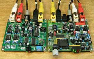
This is the 2nd generation of the AD2496 design. I'm happy meanwhile to be able to provide not only boards but also many parts to enable DIYs to reproduce the ADC.
To have a look at the previous prototype click here. There you'll find additional information not included on this page as well as a detailed description of the circuit diagram.
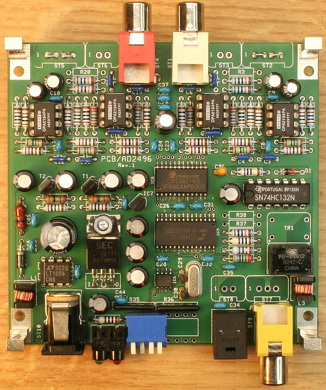
The latest circuit diagram of the AD2496 is shown here. All modifacations I intended and described in the article about the prototype have been implemented. Additionally I introduced two current compensated chokes for higher EMV immunity. Not that I experienced them to be necessary, but I know about the extreme requirements of the relevant regulations. And this design is meant to be professional.
May '06: I also found out that the TOTX141 has to be replaced by a TOTX179P because the TOTX141 is a 3.3 V type (which does actually not prevent it from working in all my units). Except its operating voltage of 5 V the TOTX179P is fully compatible. Also, the discontinued CS8405A is replaced by the fully compatible CS8406.
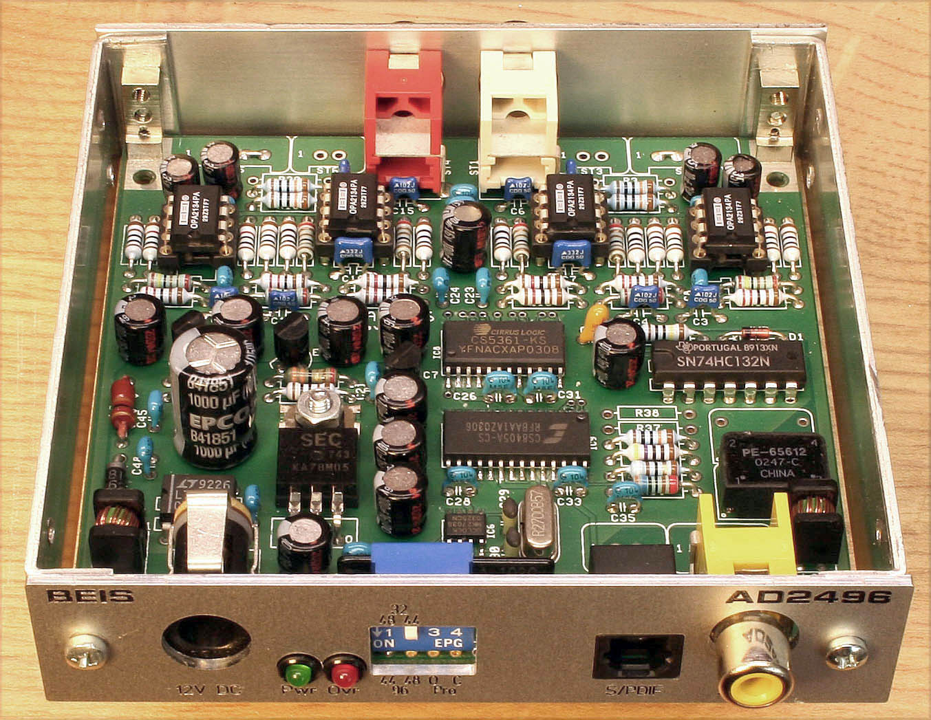
I rearranged the DIP-switches so that the 4 relevant ones are on the leftmost side. The others are for experimental use and not meant to be populated in an actual device.
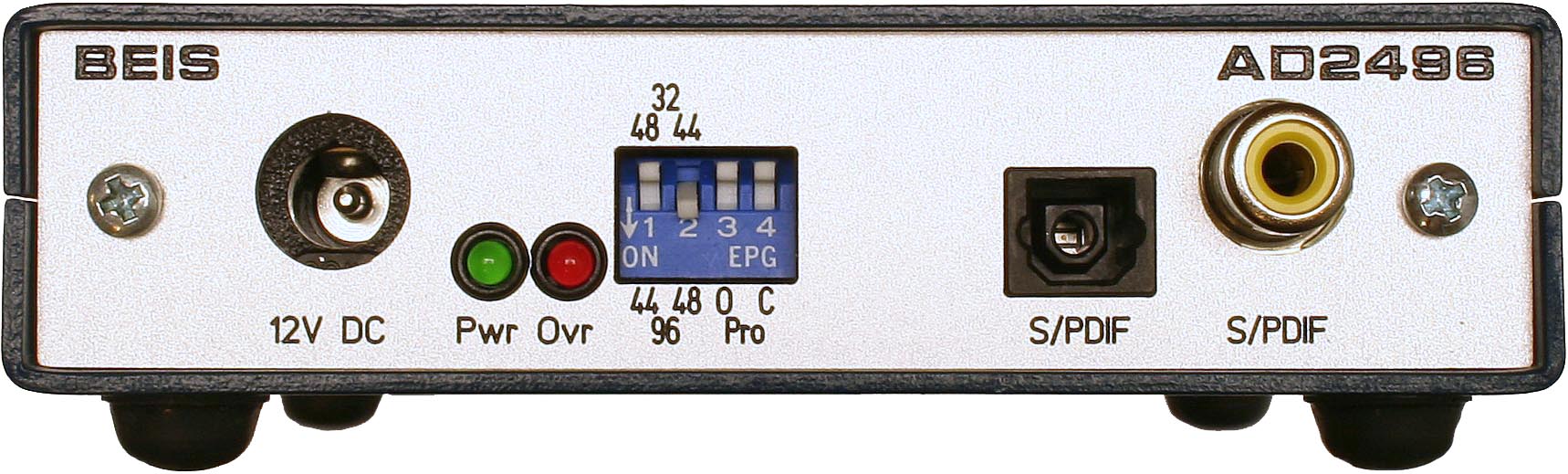
I was pointed out to a mistake I made (thank you, Ralph): Under normal circumstances the emphasis DIL-switch (SW1G, 7th switch, pins 7 and 10), should be be switched to "On". Actually, it is a "No-Empasis" switch and usually no emphasis is used. When only the 4 relevant switches are populated, the "No-Emphase" setting is "Off". The consequence is: When
the "Emphasis" bit is set and equipment that respects this bit will de-emphase the audio signal (the sound becomes dull). Note: Equipment that that supports emphase does not seem to be very common, e.g., I don't have any. But Ralph has:-)
Either:
I am sorry for that mistake.
 Read
also the article
about the high quality preamplifier I designed to fit to the
AD2496.
Read
also the article
about the high quality preamplifier I designed to fit to the
AD2496.
 Boards available
Currently I do have boards and more components (particularly those ones which are not easy to get) available for DIYs. See my Partslist and Parts Availability for AD2496 page.
Please also excuse that I'm a little bit anxious about giving away the Gerber data. I'm a professional electronics designer and meanwhile I believe my design to be really professional in all respects. I have no experience how likely it is that somebody will try to make money with the work I did - on the other hand I want to share my work with other DIYs. Of course I know that anybody who really wants to copy the board won't be stopped by having a board only instead of the original Gerber data, but what else could I do?
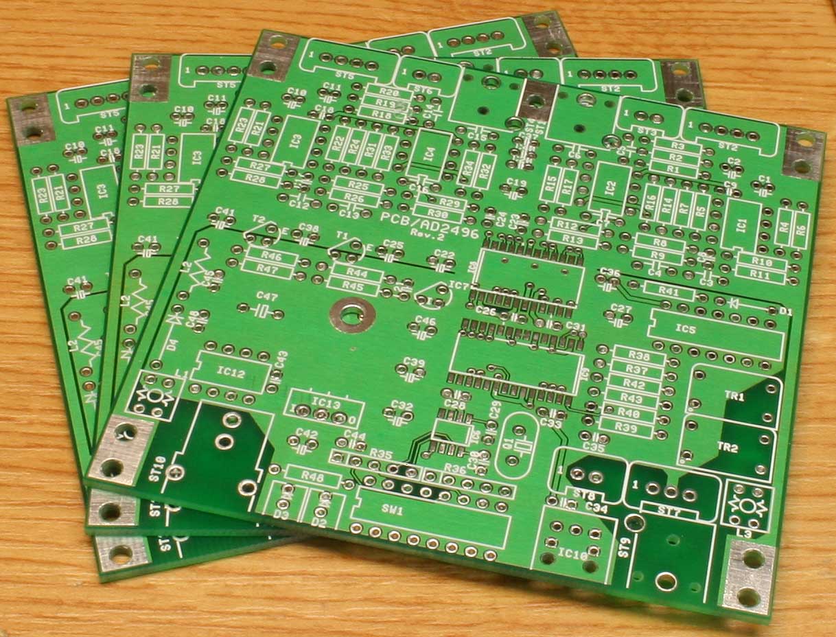
Find here two assembly drawings:
|

|
|
| Indicating the components name | Indicating the components type or value |
 For my units I used an SG206 case from the (German) company Fischer Elektronik. Front panel, case and
board are directly fixed to each other using the element 5.60.422 from the (German) company
Ettinger,
available at Bürklin. You need not necessarily use
the case I used. The board can easily be built into other cases.
For this case I provided a detailed dimensional drawing,
either as a GIF file
or as a PDF file.
You will see there how the board is fixed within the SG206 and
how it can alternatively be fixed directly to other front panels.
Of course you may also use four stand-offs, pillars or distance
tubes to fix the board on the bottom of your case. The drilling
positions can be found in the dimensional drawing, too.
For my units I used an SG206 case from the (German) company Fischer Elektronik. Front panel, case and
board are directly fixed to each other using the element 5.60.422 from the (German) company
Ettinger,
available at Bürklin. You need not necessarily use
the case I used. The board can easily be built into other cases.
For this case I provided a detailed dimensional drawing,
either as a GIF file
or as a PDF file.
You will see there how the board is fixed within the SG206 and
how it can alternatively be fixed directly to other front panels.
Of course you may also use four stand-offs, pillars or distance
tubes to fix the board on the bottom of your case. The drilling
positions can be found in the dimensional drawing, too.
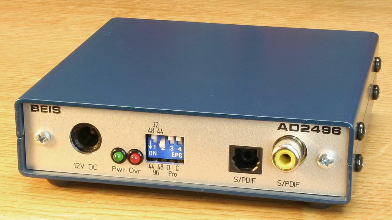
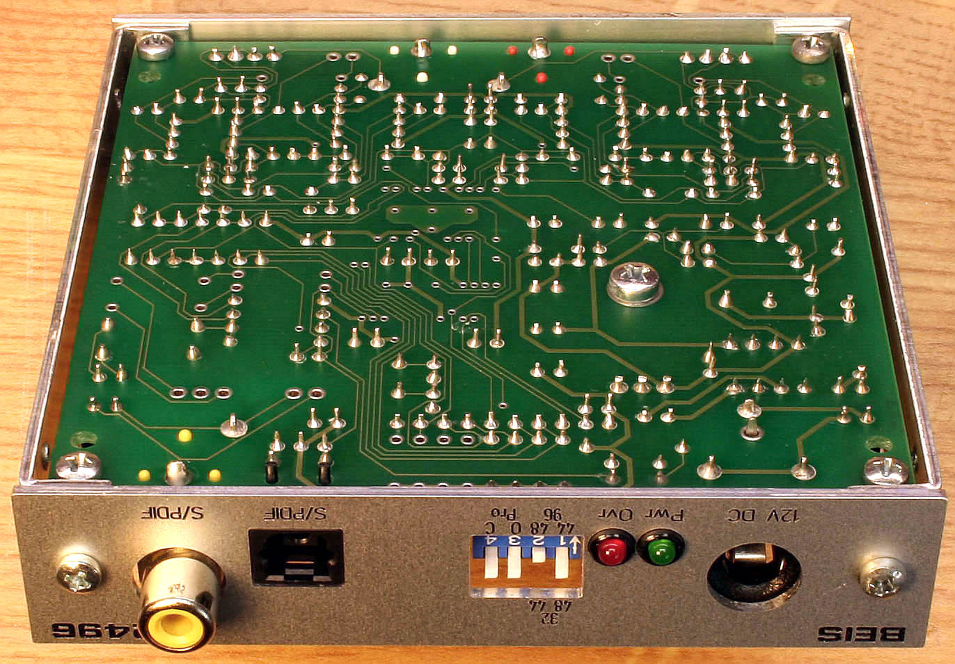
The front panel is manufactured by Schaeffer AG (in Europe) and is available in the US from Front Panel Express, LLC, too. You need the design file for the front panel, then you just have to send it to the manufacturer and you'll get a perfectly milled and engraved front panel, as the photos show. You may also modify the design file with the front panel design software "Front Panel Designer" German or English (it's free and very convenient) so that it fits to other cases of your choice. As the back panel only contains two simple 10 mm holes and maybe the markings "L" and "R" I forwent to prepare a design file for that, but it is simple to modify the front panel design file to obtain the corresponding file for the back panel.
| Last update: June, 3rd, 2007 | Questions? Suggestions? Email Me! | Uwe Beis |