|
|
|
|
|
|
These are the previous results of my 24 Bit / 96 kHz audio ADC and DAC project. The intention of this project is:
Though I spent a lot of time and money for this project I do not intend to make money with it. The material published here remains, however, my property and any commercial use requires my written consent.
Simple audio converters are cheap to buy, this of course should be significantly better. So I aimed for something more professional:
The devices were intended to be as small as possible. I decided to use THT (through hole technology, in contrast to SMT, surface mount technology), so that it is easier to reproduce them on a DIY basis. Some devices, however, are available in SMT only and some are not easy to purchase in small quantities at all. If there is enough interest I will think about organizing some kind of parts procurement. The previously described of the ADC meanwhile is redesigned, the DAC is still on the waiting list.
|
|
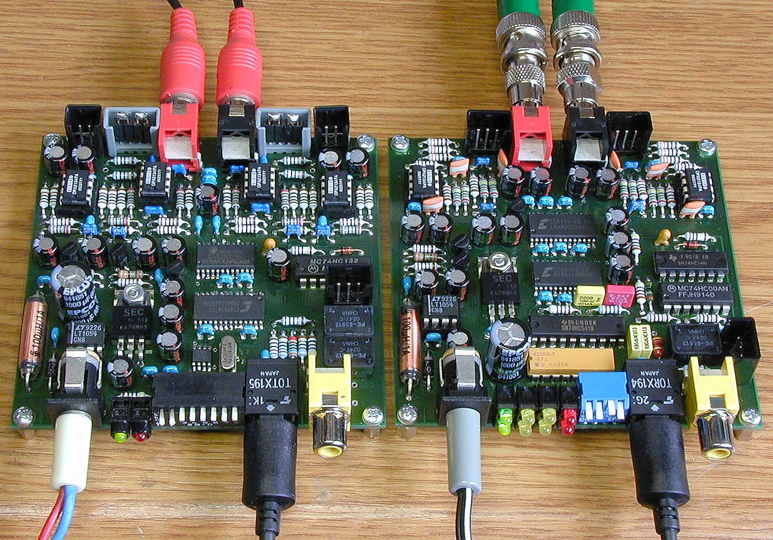
| A/D Converter AD2496 - Prototype | D/A Converter DA2496 |
System Architecture and Component Selection
The kernel of the system is based on ICs made by Cirrus Logic. I selected the CS5361 as ADC and CS4396 as DAC, the "second best" pair of A/D and D/A converters from Cirrus. The "best" ones I found to be too expensive. I took the CS8405A as digital audio transmitter and the CS8415A as receiver. Unfortunately the ICs are available as SMDs only, but you won't find modern audio converters in THT anymore. Except for the multi-frequency clock generator (earlier MK1412A, now MK2703 from ICS) all other components are i n THT. All op-amps are TI/Burr-Brown OP2134, quite good ones (and a bit more expensive).
Power supply is 12 V DC for both devices with approx. 200 mA each. Operation starts from 7 V on, so a supply from 8 V to 15 V is suitable. Internally, a negative supply for the op-amps is generated.
A processor or any other programmable IC is not employed. Currently, all logic functions are implemented in standard HC-MOS logic. Meanwhile it turned out, that a small processor would be an improvement.
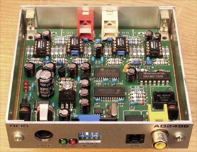
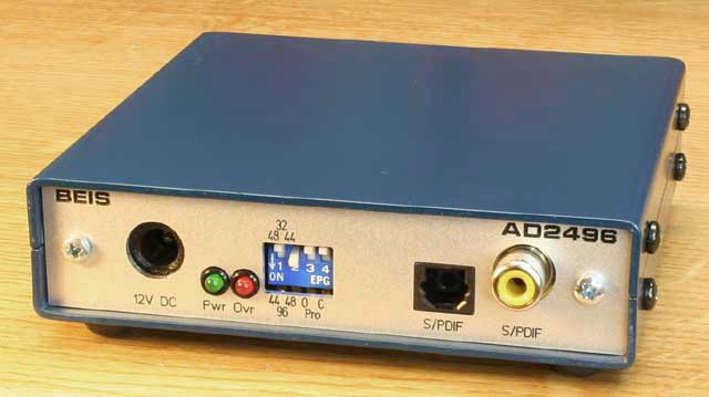
The enclosure I chose was an SG206, 25 mm x 100 mm x 100 mm. The front panel is milled and engraved and is not very cheap but looks very professional:
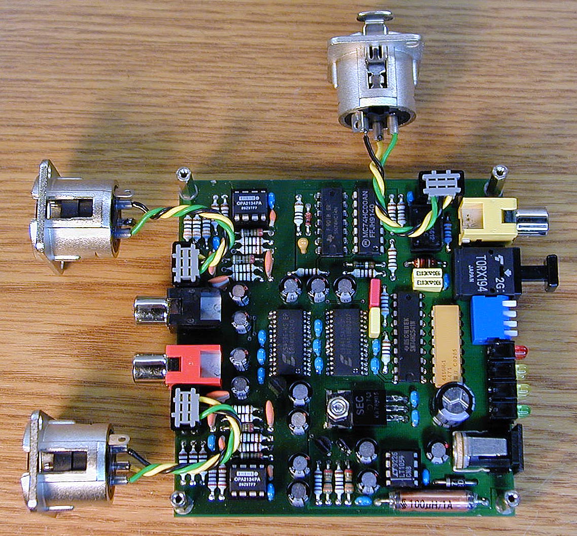
The versions with AES3 and balanced audio in- and outputs have 3 additional XLR connectors, and in the ADC there are some switches more. In this case the enclosure will become 50 mm high (SG208).
System Performance
I do not own the professional measurement equipment that would be appropriate for this kind of electronics. My distortion meter is able to measure 0.01% (-80 dB) of distortion. About 100 times better would be appropriate here. I cannot measure jitter or intermodulation at all. But what I can measure is, of course, the signal to noise ratio and the frequency response.
The ADC's (CS5361) SNR-performance is specified to be typically 111 dB (unweighted) and the DAC's specification i s 117 dB (unweighted). For both, ADC and DAC in series, 110 dB are to be expected. I measured 103 dB, and that is a bit disappointing - where are 7 dB gone? All I found out is that it is really conversion noise and no op-amp noise and no noise from the power supply. The DA2496 alone shows approx. -107 dB noise with a digital zero audio data stream.
The frequency response corresponds to what you can read in the ADC and DAC specification, with a lower frequency limit at about 0.2 Hz. This is pretty low so I raised it to approx. 2 Hz in the prototypes. For the other values I have to rely on the specifications in the data sheets.
I summarized an individual description of both devices in these two articles
24 Bit / 96 kHz Audio Analogue to Digital Converter AD2496
and
24 Bit / 96 kHz Audio Digital to Analogue Converter DA2496.
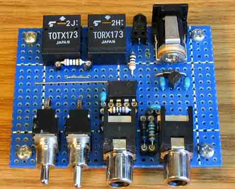
The S/PDIF Converter
In addition I designed a universal S/PDIF converter with one optical and one coax input and output each. You can buy of-the-shelf devices for little money, but they are not specified for more than 48 kHz. I tested some of them and found them to be unsatisfactory. So here is my design of a Universal S/PDIF Converter.
An Introduction to Delta Sigma Converters
In order to understand what happens inside of the ADCs and DACs I tried to find out how delta sigma converters work. It was not too easy, as all explanations I found seemed quite theoretical to me. Anyway, after some time I got through. I assume that others face the same situation so I wrote this Introduction to Delta Sigma Converters from my practical point of view.
Other Links
General information you might be interested in:
You can find a detailed description of the S/PDIF and AES3 hardware interface standards and its data structure in technote 26 from Audio Precision The AES3 and IEC60958 Digital Interface (or TECHNOTE Series by Julian Dunn The Digital Interface) or in application note AN22 from Cirrus Logic Overview of Digital Audio Interface Data Structure (data structure only).
A comprehensive collection of links related to digital audio can be found at the Digital Audio Page from ePanorama.net.
| Last update: June, 3rd, 2007 | Questions? Suggestions? Email Me! | Uwe Beis |