|
|
|
|
|
|
Once again I wrote this article because I didn't find anything else that, without being too complicated, helped me to find out how I could implement digital counterparts of analog filters. Finally I found out at least one way to do it and I believe it might be interesting for others to share my perceptions. And I want to prepare a recipe, once more without much theory and/or mathematics.
Note: In this article the term "Frequency Response" denotes all frequency depending responses of a filter, as there are:
I.e., a filter has two (or three resp.) frequency responses.
One thing you should know about any digital filter, not only those ones I'm talking about:
By nature, the frequency responses of any digital (or, to be more precise: "sampled") system is mirrored at half of the sampling rate (FS/2). As a consequence, at FS/2 any such frequency response is horizontal. This does not fit to the frequency responses of almost any analog filter. Thus:
A digital filter can never match the frequency responses of any analog model exactly, it can only approximate it. The closer the corner frequency FC to FS/2 is, the bigger the differences between both become (but often rather as an advantage than a drawback for the digital filter).
The filters described here are bilinear transformed ones. Without the bilinear transformation, alias effects within the frequency responses would occur, and this shall be avoided. Just a little background information about the bilinear transformation which modifies (or distorts, resp.) the filter's frequency axis in a way that
Have a look at an example of the difference between the original analog and the bilinear transformed digital amplitude response in case the sampling frequency FS is 4 times as high as the corner frequency FC (Example: 6th order Chebycheff, 3 dB):
Or, with a view at the stop band, down to -80 dB:
In case of ratio of FS/FC = 10 this difference of the amplitude responses is very little ("three pixel" in the pass band in the figures above, at most), and with FS/FC = 40 it is invisible.
Unfortunately, this is not the same with the phase response (and thus the group delay). These are not only distorted in the frequency axis, but also in their angle (or time resp.) axes. The smaller FS/FC is, the bigger this distortion is. You can explore this effect (and many others, of course) using AnaDigFilt.exe.
Another important approach for a conversion is based on the "Impulse Invariant Transformation", which preserves the exact impulse response of the analog prototype. For 1st order filters I described it in another article Simple Conversion of Single Pole Analog into Digital (IIR) Filters.
Unfortunately, due to the facts explained above, there are a couple of applications where it makes few sense to convert an analog solution into a digital one. This is the case when a specific amplitude response is required and must perfectly be matched.
In this article I predominantly describe filters with a pass band and a stop band. With these filters usually only a certain ripple within the pass band and a certain gain within the stop band shall not be exceeded while the exact amplitude response within both bands is less important.
But with other filters it is often required that a specific amplitude response must be abided over the whole band of interest (which can be up to FS/2 in the digital domain only, of course). Maybe the expression "filter" even would not be correct for these kinds of applications. Examples are:
One might find sufficient approximations for given applications, but never an exact conversion. As already mentioned, this is theoretically impossible. Approximations will be most satisfying when either the differences in the amplitude responses at higher frequencies (particularly close to FS/2) are not too important or when huge efforts are made, e.g. with lots of IIR stages or using FFT and IFFT for the filter, or by filtering an upsampled signal.
Also, as mentioned above, it must be kept in mind that the phase response (and thus the group delay) of pass and stop band filters is not precisely transformed, but more or less distorted.
And, of course, when the exact impulse response must be preserved, the "Impulse Invariant Transformation" is the best choice.
The filter structures I explain and use in this article are based on the so called Direct Form II, even though other filter structures are possible and, depending on the operating conditions, may have advantages.
![]() denotes a multiplier with a constant
factor (the coefficient b0 in this case),
denotes a multiplier with a constant
factor (the coefficient b0 in this case),
![]() indicates an adder and
indicates an adder and
![]() is a delay of one sample clock,
i.e., a register in practice.
is a delay of one sample clock,
i.e., a register in practice.
BTW, on the left hand side, with the "a" coefficients, you see an IIR while the right hand side with the "b" coefficients forms an FIR filter.
Shown above is a 2nd order digital filter. In a 1st order one the coefficients -a2 and b2 both are zero and thus the second delay register and two adders can be omitted:
Note: 1st order analog filters are usually converted into 2nd order digital ones.
Here I presume it to be known how to implement such filter algorithms in soft- or hardware, whichever your target is. I want to explain how to find out the coefficients a1, a2, b0, b1and b2 for a given analog filter.
Before I do this, let me explain a slight variation of the filter diagrams above, which in many cases makes the practical implemention a little easier and more efficient:
At first the input value is multiplied by the coefficient b0 which is now named k, and so the coefficient b'1 results from b1/b0 and b'2 from b2/b0. The advantage of this variation is that b'1 and b'2 in practice often become 2 or 1 resp., so that one multiplier can be replaced by a simple shift operation and another one can be omitted completely.
One more variation of the filter structures above worth mentioning are their transposed forms:
A prerequisite for the "recipe" I want to introduce here is that the analog filter can be represented in the form of one or more cascaded 1st and 2nd order filter stages.
A circuit diagram, for example, might look like this:
This is a 5th order (and thus a cascaded 3 stage) low-pass filter. By the way, in case you want to build or simulate this analog circuit you can use this tool to dimension the resistors and capacitors.
Mathematically spoken, the general formular for the transfer function of any 2nd order analog filter looks like this:
For a simple 2nd order analog low-pass filter, the transfer function is significantly more simple (stage gain = 1 assumed):
and, for the example of an analog 5th order low-pass filter above with the stages i = 1, 2 and 3, the entire transfer function is H(ω) = H1(ω) · H2(ω) · H3(ω):
This 5th order analog filter would be transformed to a 5th order (and thus again a cascaded 3 stage) digital filter, like this:
(Note: In an actual conversion, e.g. using AnaDigFilt.exe, due to the bilinear transformation, all 1st order stages would be converted to 2nd order ones.)
The general formular for the transfer function of a 2nd order IIR filter looks similar to the analog one:
or, equivalent:
Usually this transfer function is normalized so that a0 = 1 (that's why there are no coefficients a0i in the diagram above):
and furthermore I use the form shown in Fig. 4, where K = b0, b'0 = 1, b'1 = b1/b0 and b'2 = b2/b0 (that's why there are no coefficients b'0i in the diagram above):
The transfer function for a simple, bilinear transformed low pass filter looks little easier only. Like for transfer functions of higher order analog filters, for transfer functions of higher order digital filters all transfer functions of each individual stage must be multiplied with each other, i.e., H(z) = H1(z) · H2(z) · H3(z).
Now, prior to conversion of the analog into a digital filter, it is up to you to determine the coefficients of the analog filter. As already mentioned, actually it is not the scope of this article to explain how to do this, but at least I'd like to point out: In case you need a standard filter like Bessel, Butterworth or Chebycheff, either as low-pass, high-pass or other one, you have two choices:
Choice a) You'll find the transfer functions and the coefficients in many tables like in this in-depth article at the TI-website. Note: In my article the coefficients are named c1 and c2 while there (and in many other publications) they are named a and b, resp.. They are listed for ω = 1, i.e., for f = 1 / (2 · π) = 0.159 Hz approx. and must be corrected for the desired corner frequency FC:
c1 = a / (2 · π · FC)
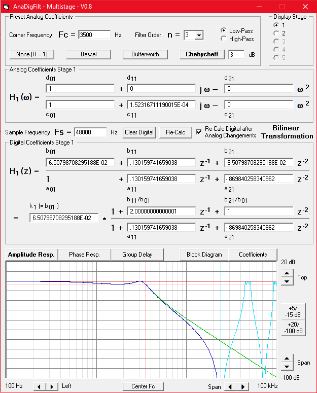
c2 = b / (2 · π · FC)2Choice b) Use my little program AnaDigFilt.exe which I wrote for this application, select your filter characteristics, filter order and corner frequency and you will not only get all analog coefficients but also the converted coefficients for the digital transfer function as well as all frequency responses of both filters.
Neither of these choices will help you to find the coefficients in case you have a more complex filter, like a band-pass, band-stop or elliptical one. But once you know the coefficients, AnaDigFilt.exe can help you to convert the coefficients even of these filters, at least.
It is quite a straight forward calculation, well suited for the "recipe" I want to provide.
First, you need a faktor g which depends on the relation of the filter's corner frequency FC and the system's sampling frequency FS.
g = 1 / (tan(π · FC / FS))
g has to be corrected with the actual frequency and becomes gn:
gn = g · 2 · π · FC or gn = (2 · π · FC) / (tan(π · FC / FS))
The following calculations must be done for each stage i independently.
As an intermediate result it is advisable to previously calculate cc:
cci = c0i + gn · c1i + gn2 · c2i
Now the calculation of a1i, a2i, b0i, b1i and b2i can start (a0i is always = 1):
b0i = (d0i + gn · d1i + gn2 · d2i) / cci
b1i = 2 · (d0i - gn2 · d2i) / cci
b2i = (d0i - gn · d1i + gn2 · d2i) / ccia0i = 1
a1i = 2 · (c0i - gn2 · c2i) / cci
a2i = (c0i - gn · c1i + gn2 · c2i) / cci
Yes folks, that's all(!).
Note on 1st order high-pass filters: When the digital coefficients are derived with this algorithm, a0 + a1 + a2 = 0. In practice, such a digital filter internally forms an integrator which works perfectly until it overflows. To overcome this, use for 1st order high-pass filters:
b'0 = b0 b'1 = -b2 b'2 = 0
a'0 = 1 a'1 = -a2 a'2 = 0
BTW, talking about the denominator in H(z): The sum of its coefficients tells about the value that the internal delay registers reach in case of a constant (i.e., DC) input value, which is usually the maximum register value that can arise under worst case circumstances. This maximum value is Input_Value * 1 / (a0 + a1 + a2).
Though I'm not a professional programmer I wrote this little program in Visual Basic for myself in order to gain experiences with the perceptions about filter conversions I got. By and by it became more and more comfortable and meanwhile I believe, for many others it can be a great help for this subject matter.
You can dowload the latest version here as a ZIP file. There is no installer. AnaDigFilt.EXE can simply be copied into any directory of your choice. Before you run it, you need to copy MSVBVM50.DLL either into the same directory or into C:\WINDOWS\system32\, where DLLs are usually located.
This program is free, of course, but I do not guarantee it to be free of errors. Should your hobby be to find out how to crash programs: Feel free, you will soon have sense of achievements.
I'd rather provide this as Java Script, but it is beyond my capabilities to realize dynamic, server based picture generation and I find the frequency responses to be too important. So I wrote it in Visual Basic and provide it as a downloadable EXE-file (which is quite likely to be free of malicious code - for years I haven't had a virus or so on my PC).
In AnaDigFilt you can:
This is represented by the program's block diagram:
The frequency responses you can view are (click for a preview) :
For my point of view it is particularly interesting to "play" with the digital coefficients and to explore the consequences. Often, these consequences are astonishingly little. E.g., when you have a standard low-pass filter, you will find that all b'1i = 2 and b'2i = 1. Try to set them to zero and multiply k by 4: Especially with FS/2 >> FC the difference in practice may be negligible. In the final design this can significantly reduce the necessary calculations.
Also, the reduction of the digital coefficient's precision to a couple of bits with the consequences of slightly different frequency responses can often be tolerated for the sake of optimization of the code. For example, with a precision of 6 bits you can replace each multiplication averagely by 3 shift-and-add operations. And a precision of six bits implies a precision of better than +/- 1% - better than you will be able to achieve with an analog filter.
A simple 1st order low-pass filter with FS = 10 kHz and FC = 10 Hz. In order to illustrate the cruicial points, I simplified the digital filter to a 1st order one and additionally set b1 = 0 in the digital domain:
and with the resulting
k = 0.00628 (= 2 · π / 1000) and
a1 = -0.99372 (= k - 1)
the algorithm becomes:
0.99372 is so close to 1 that the difference seems to be negligible and a1 could be set to 1, but this is wrong. With a1 = 1 the filter would become an integrator integrating its own output value until it overflows. This means: The difference between a1 and 1 must be as precise as a1 itself, or, better: a1 must be exactly 1 - k. Otherwise the DC gain will be different from 1.
The signal's word width is assumed to be 8 bit, the multiplicators are assumed to support 8 x 8 bit, too. In order to represent k = 2 · π / 1000 (which as a binary value is 0.00000001100110111100011001011011) as an integer input value for an 8 bit multiplier, it can be multiplied with the highest value 2n that gives a result < 28. In this case it is n = 15. I.e, the multiplicator will be shifted 15 bit left.
k = (2 · π / 1000) · 215 = 205.887, which must be rounded to 206. Once the input signal is multiplied by 215, the signal width becomes 8 + 15 = 23 bit. This is the word width you have to work with. Of course, the output signal must finally be divided by 215 again, i.e., shifted by 15 bit, which does not mean anything else but to use the most significant 8 bits out of the 23 bit output word only:
The next step is to implement the multiplication with 0.99373. As we have 8 bit multipiers, it is best to multiply by 0.00628 (just like above) and subtract that from 1:
Because the signal is shifted by 15 bit already, the multiplication of 0.00628 again becomes one of 206, shifted to the last significant bits of the accumulator. In hardware, it would look like this:
An important issue is the width of the accumulators to be used. The greater FS/FC is, the wider they become. In the example above one can see that the accumulator is 15 bit wider than the in- and output signal. Would it be made more narrow, the output value in case of an input step due to truncation effects would never reach the input value.
You can use floating point operations if your hardware supports it. For me this is like breaking a fly on the wheel (or shooting with canons at sparrows, as we say in Germany). But it should work
What happens in the example above, if we use the most significant two bits of the coefficients only? Originally k was = 0.00000001100110111100011001011011, and, abbreviated to 8 bit, became = 0.000000011001101. As the first two 1-bits are followed by two 0-bits the difference is not too high when we omit every digit after the first two 1-bits, i.e., k becomes 0.000000011, which is = 0,00586. Thus the corner frequency will differ 0.00586/0.00628 = 7% which might be acceptable.
The advantage is: The multiplicator is 3 (instead of 206) only, which is easy to implement using one shift and one add instruction (i.e., no need for a multiplier), and the word width is reduced from 23 to 17 bit.
In a digital system after almost each amplitude change the result must be rounded to the output word width. Rounding means producing errors, i.e., quantizing errors in general. If in a cascaded system at each stage the intermediate result is rounded to the input word width, in each stage 3 dB of noise is added. I.e., 3 dB in case of one stage, 4.7 dB in case of two and 6 dB in case of four stages, for example.
The noise in such a multistage environment can drastically be reduced (down to 3 dB, in best case) when the intermediate results are not truncated, or at least not to the output word width.
You must always be aware which minimum and maximum values can be reached in each stage of your filter. An over- or underflow causes catastrophical results and limiting ("clipping") the adder output values as a precaution might be good idea, but it should never be necessary, of course. A simple, 1st order low-pass filter like the one above will never exceed the input's range of values internally. In higher order (multistage) low-pass filters this can very well be the case, and should you reverse the usual (from low Q to high Q) order of stages, the range of values of the first stage can be a multiple of the input's one.
In case of floating point operations, of course, you once again don't have to care about that.
One thing that weighs heavily on my mind is actually not really a matter of technique. It is a matter of the exact use of terms. While I was writing about "digital" in contrast to "analog" filters, I actually was wrong. And so many or almost all other authors are, too:
The so-called "digital" filter techniques and algorithms are based on "sampled" (= time discrete) signals, not necessarily on digital (quantized) ones.
The term "Digital Filter" is usually used incorrectly. Correct would be the use of "Time Discrete Filter" (or similar).
I know, I won't be able to convince the rest of the world to use the correct terms. Not even I will do it myself. (*Sigh*)
| Last update: January 11th, 2025 | Questions? Suggestions? Email Me! | Uwe Beis |